")
")
")
")
")
")

AVAILABLE IN TWO VERSIONS: DomBus protocol and Modbus protocol!
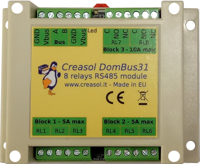
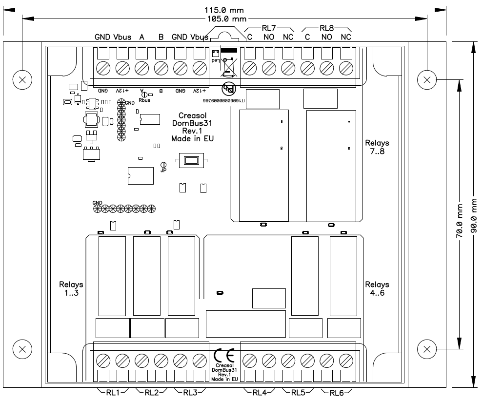
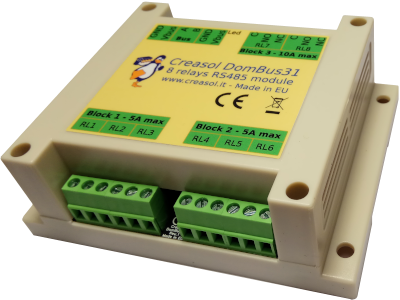
Creasol DomBus31 is a din-rail relay module, 115x90x40mm, with 8 relays outputs. 6 relays are SPST (Normally Open outputs) with 250V 5A max capability, and 2 relays are SPDT (both Normally Open and Normally Closed outputs) with 10A capability. High efficiency module, with very low power consumption, only 600mW with all relays ON.
The English language page contains the updated information As other DomBus devices, DomBus31 provides excellent performance in terms of power optimization: with all 8 relays active (the worst case), the power consumption is only 600mW! As a comparison, KMTronic 8 relays module consumes 12W, Denkovi 8 relays board consumes about 3W, Sonoff Dual R2 consumes 2W with only 2 relays enabled.
It's available with two firmware types: DomBus (proprietary protocol with enhanced features) for Domoticz controller, and Modbus RTU (standard protocol working with almost any home automation system). Check below for a detailed comparison between the two protocols.
It uses a RS485 industrial-grade serial bus, using a common shielded cable with 4 wires: 2 for 12/24V power supply, and 2 for data at 115200bps 8,n,1 (or other speed/parity in case of Modbus RTU).
It supports two different protocols (at puchase time, select the needed protocol!):
- DomBus protocol, that is supported by Domoticz home automation controller, is a reliable multi-master protocol that permits to manage dozens of modules and get status from a module as soon as it changes. Also it includes the so-called DCMD commands that, similarly to KNX, are transmitted between DomBus modules in the same bus to activate outputs, scenes and groups in case of events without needing for the intervention of the home automation controller, useful solution to get a home automation system working even in case of domotic controller fault. Check below for an explanation about DCMD.
The Creasol DomBus plugin have to be installed in Domoticz, using the Python Plugin Manager or downloading the software from GitHub (see the section below). - Modbus RTU protocol, widely used in industrial and home automation systems, is supported by almost any domotic controller like Home Assistant, OpenHAB, IObroker, Node-RED, ...
Modbus is a master-slave protocol that permits to activate and deactivate a single relay or a group of relays by a single command. Also, it's possible to specify, for each relay, the ON time from 31.5ms to 1500 days, so the relay automatically switches OFF after the selected time.
Confused about the two versions? If you use Domoticz, DomBus version is much better because includes enhanced features like DCMD and autodiscovery. For other building automations, Modbus version should be chosen because compatible with almost everything.
Ask for support on Telegram group https://t.me/DomBus
The RS485 serial bus is the ideal solution to get:
- easy wiring and connection: use a common thin alarm cable within 4 wires, 2x0.5mm² wires for 12V power supply, and 2x0.22mm² wires for data. This is much easier and better than ethernet UTP/STP connections.
- robustness differential signalling permits to connect about 30 modules with more than 200m total distance. Modules can be connected together using a mix of linear/star bus topology.
- very low power consumption: each module is supplied at 12V and has inside an high efficiency switching mode converter to minimize the power comsumption.
- power outage tolerant: using a 13.6V power supply with lead acid battery it's possible to supply domotic network, IPCams, NVR, switches, routers, so the system keeps working even in case of power cut-out.
- no RF pollution, no batteries to change
For large building, to improve the bus reliability, it's possible to make more than 1 bus so in case of fault, only the bus with fault stops working.
Features
- 6 relay outputs, SPST (normally open contact on screw terminal block) with 250Vac/30Vdc 5A contact (max 30Vdc in case of DC load, 250Vac in case of AC load).
- 2 relay outputs, SPDT (normally open and normally closed contacts on screw terminal block) with 250V 10A contacts.
- Relays are divided in 3 blocks, each block respects the creepage distance from other blocks. Do not mix high and low voltage signals inside the same block!
- 8-35Vdc power supply (internally regulated by a switching mode power supply circuitry that minimize power consumption and dissipation).
- low power consumption: 0.75mA @12V (9mW) stand-by current with all relays OFF, and 50mA @12V (600mW) with all relays ON.
- 115200 bps RS485 bus (max length: 1km), 8 bit data, no parity, 1 stop bit. Bitrate and parity may be changed in the Modbus version.
- To do a factory reset, remove power supply to the module, short the JP jumper on the PCB (with a tin ball), and power on again: a short flash on LED red will be emitted.
- DCMD supports (DomBus firmware only): this is a feature (described below) that permits to get easy automations without writing a line of code, and command exchanged between DomBus modules even in case that domotic controller is stopped. For example configuring a pushbutton input port as
DCMD(Pulse)=11.3:Toggle, DCMD(Pulse1)=0.7:Toggle, DCMD(Pulse2)=0.8:On
it's possible:
* with a short 0.5s pulse, toggles on/off port #3 output of DomBus module #11
* with a 1s pulse, toggle on/off a group of switches on the controller
* with a 2s long pulse, activate a scene that, for example, disable all lights/loads and activate the alarm system (useful when leaving the building).
Warnings
- Relays are divided in 3 blocks: do not mix high voltage (230V) loads and low voltage (5/12/24V) loads on the same terminal block!
- Do not use capacitive loads with high inrush current (bad power supplies, ballasts, ...) otherwise the relay contact may weld.
- Use a 4 wires shielded cable for the bus, using two lines to send power supply (12-14Vdc) protected by a fuse.
- To reduce noise and reflections on the bus, enable the termination resistor (shorting Rbus PCB jumper) on the two furthest ends of the bus.
DomBus31 DomBus capabilities (for the DomBus firmware version)
Default address: 0xff31
| Port# | Name | Capabilities | Default configuration | Description |
| 1 | RL1 | OUT_DIGITAL, OUT_RELAY_LP, OUT_BLIND | OUT_RELAY_LP | SPST relay output, NO contact, 5A 250Vac or 30Vdc output capability. Relay contact is protected by varistor |
| 2 | RL2 | OUT_DIGITAL, OUT_RELAY_LP, OUT_BLIND | OUT_RELAY_LP | SPST relay output, NO contact, 5A 250Vac or 30Vdc output capability. Relay contact is protected by varistor |
| 3 | RL3 | OUT_DIGITAL, OUT_RELAY_LP, OUT_BLIND | OUT_RELAY_LP | SPST relay output, NO contact, 5A 250Vac or 30Vdc output capability. Relay contact is protected by varistor |
| 4 | RL4 | OUT_DIGITAL, OUT_RELAY_LP, OUT_BLIND | OUT_RELAY_LP | SPST relay output, NO contact, 5A 250Vac or 30Vdc output capability. Relay contact is protected by varistor |
| 5 | RL5 | OUT_DIGITAL, OUT_RELAY_LP, OUT_BLIND | OUT_RELAY_LP | SPST relay output, NO contact, 5A 250Vac or 30Vdc output capability. Relay contact is protected by varistor |
| 6 | RL6 | OUT_DIGITAL, OUT_RELAY_LP, OUT_BLIND | OUT_RELAY_LP | SPST relay output, NO contact, 5A 250Vac or 30Vdc output capability. Relay contact is protected by varistor |
| 7 | RL7 | OUT_DIGITAL, OUT_RELAY_LP, OUT_BLIND | OUT_RELAY_LP | SPDT relay output, NO + NC contacts, 10A 250Vac or 250Vdc output capability. Relay contact is protected by varistor |
| 8 | RL8 | OUT_DIGITAL, OUT_RELAY_LP, OUT_BLIND(1) | OUT_RELAY_LP | SPDT relay output, NO + NC contacts, 10A 250Vac or 250Vdc output capability. Relay contact is protected by varistor |
(1): can be used as BLIND output, to open a blind/curtain, but only the previous port can be configured in Domoticz as OUT_BLIND because, when configured as OUT_BLIND, DomBus device automatically configure the next port to drive a relay in open direction.
DomBus31 Modbus RTU capabilities (for the Modbus version)
At power-on, the module shows on red LED the current Modbus slave address (register address=8192) in decimal format, on green LED the serial baudrate (reg. 8193), and finally on red LED the serial parity (reg. 8194).
If a value is zero, a long flash is emitted.
For example, if reg(8192)=54, reg(8193)=4, reg(8194)=0, at power the following led flashes will be shown:
5 red flashes, pause, 4 red flashes (slave address=54), pause, 4 green flashes (reg(8193)=4 => baudrate=9600bps), pause, 1 long red flash (reg(8194)=0 => parity=None).
Device will be operative only after showing the power-on modbus parameters led flashing: then module will accept commands by Modbus RTU, and periodically shows output status for all ports, from 1 to max port: green flash means that port status is Off, red flash means that port is On.
Default slave address: 49 (0x31)
| Addr | Name | Values | Description |
| 0 | RL1 | 0=OFF, 65280=ON, 1-65279=ON for specified time | SPST relay output, NO contact, 5A 250Vac or 30Vdc output capability. Relay contact is protected by varistor |
| 1 | RL2 | 0=OFF, 65280=ON, 1-65279=ON for specified time | SPST relay output, NO contact, 5A 250Vac or 30Vdc output capability. Relay contact is protected by varistor |
| 2 | RL3 | 0=OFF, 65280=ON, 1-65279=ON for specified time | SPST relay output, NO contact, 5A 250Vac or 30Vdc output capability. Relay contact is protected by varistor |
| 3 | RL4 | 0=OFF, 65280=ON, 1-65279=ON for specified time | SPST relay output, NO contact, 5A 250Vac or 30Vdc output capability. Relay contact is protected by varistor |
| 4 | RL5 | 0=OFF, 65280=ON, 1-65279=ON for specified time | SPST relay output, NO contact, 5A 250Vac or 30Vdc output capability. Relay contact is protected by varistor |
| 5 | RL6 | 0=OFF, 65280=ON, 1-65279=ON for specified time | SPST relay output, NO contact, 5A 250Vac or 30Vdc output capability. Relay contact is protected by varistor |
| 6 | RL7 | 0=OFF, 65280=ON, 1-65279=ON for specified time | SPDT relay output, NO + NC contacts, 10A 250Vac or 250Vdc output capability. Relay contact is protected by varistor |
| 7 | RL8 | 0=OFF, 65280=ON, 1-65279=ON for specified time | SPDT relay output, NO + NC contacts, 10A 250Vac or 250Vdc output capability. Relay contact is protected by varistor |
| 255 | All relays | bitmask: 1=> RL1, 2=>RL2, 4=>RL3, 8=>RL4 |
This address is used to set ON or OFF (no timer function) relays using a short command, by accumulating the bitmask for each relay that should be ON: for example |
| 256-263 | Port config | 1=OUT_DIGITAL, 2=OUT_RELAY_LP | Command used to configure port 1 (256) to 8 (263) as OUT_DIGITAL or OUT_RELAY_LP (low power consumption relay). |
| 512-519 | Port option | 0=NORMAL, 1=INVERTED (output normally ON) | Set port option. If set to 1, relay stays ON after boot until the port is asserted (then relays goes OFF) |
| 8192 | Slave Address | 1-247 | Permits to change the slave address of the module, so it's possible to add other modules to the same bus |
| 8193 | Serial bitrate | 0=115200bps, 1=57600, 2=38400, 3=19200, 4=9600, 5=4800, 6=2400, 7=1200bps | Serial speed, default 115200 bps 8,n,1 |
| 8194 | Serial parity | 0=None, 1=Even, 2=Odd | Serial parity, default none (115200 bps 8,n,1) |
| 8198 | Revision, major | Read only | Get firmware version, major number. For example "02" means that revision is "02XX" where XX defined by parameter 8199 |
| 8199 | Revision, minor | Read only | Get firmware version, minor number. For example "h1" means that revision is "XXh1" where XX defined by parameter 8198 |
It's possible to activate one or more outputs for a certain amount of time (monostable/timer output) as indicated in the table. The parameter corresponding to the needed time can be computed using the following rules:
From 0 to 60s => 31.25ms resolution 1=31.25ms, 1920=60s => value=time_in_milliseconds/31.5
From 1m to 1h with 1s resolution 1921=61s, 3540+1920=5460=1h => value=(time_in_seconds-60)+1920
From 1h to 1d with 1m resolution 5461=1h+1m, 1380+5460=6840=24h => value=(time_in_minutes-60)+5460
From 1d to 1500 days with 1h resolution 6841=25h, 6842=26h, and so on => value=(time_in_hours-24)+6840
The following tables show some Modbus commands examples.
| Slave Addr | Func. Code | Reg.Addr | Reg.Value | Frame | Description |
| 49 | 06 | 8192 | 1 | [31][06][20][00][00][01][46][3A] | Change slave address from 49 (0x31) to 1 |
| 01 | 06 | 8193 | 4 | [01][06][20][01][00][04][D2][09] | Set serial speed to 9600bps |
| 01 | 06 | 8194 | 1 | [01][06][20][02][00][01][E2][0A] | Set even parity |
| 49 | 10 | 8192 | 1,4,1 | [31][10][20][00][00][03][06][00][01][00][04][00][01][B1][71] | With a single command, set slave address to 1, serial speed to 9600bps, even parity. |
| 01 | 06 | 0 | 65280 | [01][06][00][00][FF][00][C8][3A] | Activate RL1 output forever (65280=0xff00) |
| 01 | 06 | 1 | 960 | [01][06][00][01][03][C0][D8][AA] | Activate RL2 for 960/32=30s |
| 01 | 06 | 255 | 0 | [01][06][00][FF][00][00][B9][FA] | Disable all outputs (Reg.Addr=255) |
| 01 | 10 | 0 | 32,0,0,65280 | [31][10][00][00][00][04][08][00][20][00][00][00][00][FF][00][E6][5C] | Set RL1 On for 1s (32), RL2 Off, RL3 Off, RL4 On - Max 10 registers can be set in one command |
| 01 | 03 | 255 | 1 | [01][03][00][FF][00][01][B4][3A] | Read a 16bit value with ports status. For example if returned value is 0xd1 (0b11010001), output status is: RL8=On, RL7=On, RL6=Off, RL5=On, RL4=Off, RL3=Off, RL2=Off, RL1=On |
| 01 | 03 | 8198 | 2 | [01][03][20][06][00][02][2F][CA] | Read 4 bytes within module version. For example, if returned value is <30><32><68><31> (in hex format), the corresponding ASCII value is "02h1" (Firmware 02h1) |
| 01 | 0F | 0 | 8,1,0xd1 | [01][0F][00][00][00][08][01][D1][3E][C9] | Set coil status to 0xd1 (0b11010001), activating RL8, RL7, RL5, RL1 and disabling other relays |
| 01 | 01 | 0 | 8 | [01][01][00][00][00][08][3D][CC] | Read coil status. If returned value is 0xd1 (0b11010001), it means that RL8, RL7, RL5 and RL1 are On |
Modbus protocol can be tested easily using a modbus program, like mbpoll for Linux:
mbpoll -v -m rtu -0 -1 -a1 -b115200 -Pnone -r 0 /dev/ttyUSB0 32 0 64 128 0 0 0 65280
to activate RL1 for 1s, R3 for 2s, RL4 for 4s and RL8 forever.
mbpoll -v -m rtu -0 -1 -a1 -b115200 -Pnone -r 255 -c 1 /dev/ttyUSB0
to read all port states.
Application notes
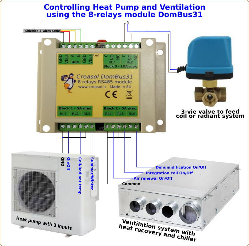
Heating/ventilation system
The following simple diagrams represents the connection to a heat pump (controlled by low voltage signals), a ventilation system (controlled by low voltage signals) and a 3-vias valve (supplied by 230Vac).
With Domoticz it's easy to get heating/cooling system with heat pump, optimized to consume most energy from photovoltaic, and a air renewable controlled mechanical ventilation with chiller and coil that regulates the relative humidity to get the maximum comfort.
For security reasons, do not mix high and low voltage loads in the same block! For example it's not safe to connect, on Block3, a 230V valve to RL8 and a 12/24V valve to RL7! On each relay block it is possible to use only low voltage or only high voltage loads.
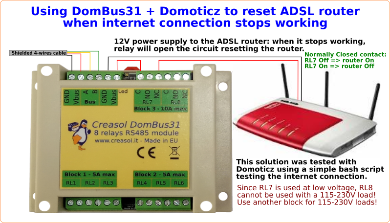
ADSL router controlled by Domoticz script to prevent hang-up
The following schema shows how to use the normally-closed contact of SPDT relay to supply a router.
A script will check that internet is working, and in case of failure activate the reset to turn power supply OFF for 10 seconds, resetting the router.
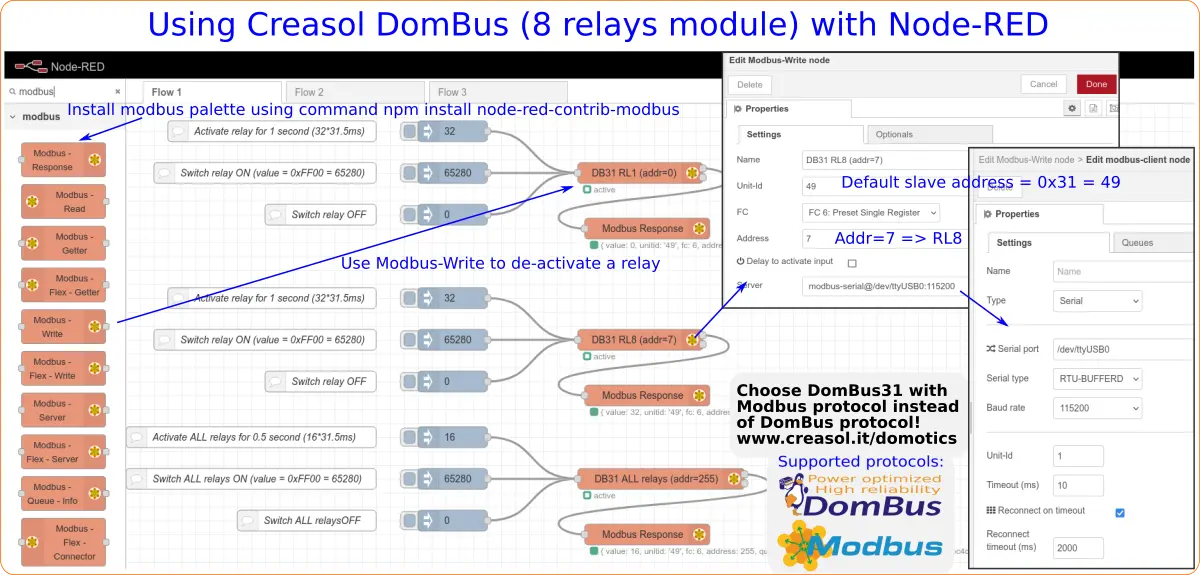
Using DomBus31 with Modbus protocol with Node-RED
To be used with Node-RED, please assure that Modbus RTU version of DomBus31 has been chosen.
Install the modbus palette using the command npm install node-red-contrib-modbus
Creasol DomBus31 is factory programmed to use default slave address = 49 (0x31, can be modified through register 8192), using serial parameters 115200, 8bit, no parity, 1 stop bit.
More information in the Node-RED page
Using DomBus 8 relays module with Home Assistant
DomBus31, with Modbus firmware, can be used with Home Assistant using the Modbus integration.
More info about DomBus modules with HomeAssistant, and configuration examples.