
Please check the page in English to have the up-to-date information without translation mistakes.
 Everybody using an electric vehicle wants to charge the car in a smart way:
- preventing overloads
- using only energy from photovoltaic, from Spring to Autumn, expecially when energy price goes low or negative
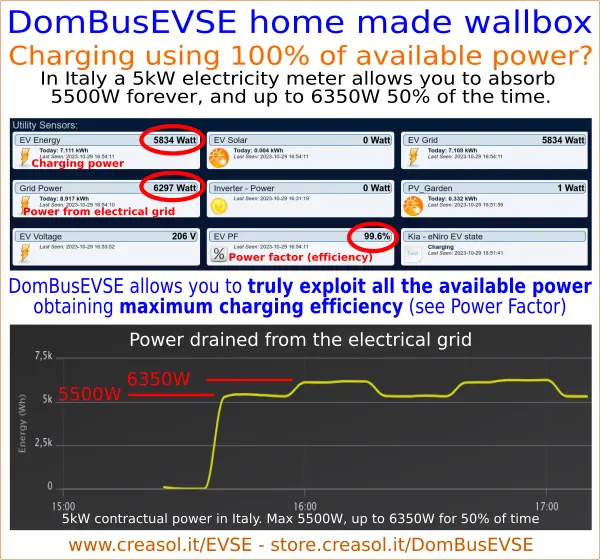
- maximizing power factor to get the highest charge efficiency
![Video showing how Power Factor increases with charging power]()
- controlling and monigoring charging by smartphone/tablet/PC
- integrating the wallbox in the home automation system, to get an efficient load balancing and accumulating energy in the car when energy price is lower
- charge the vehicle, when it's almost full, by using the minimum power to keep voltage below 253V (preventing inverter derating or disconnection)
![]()
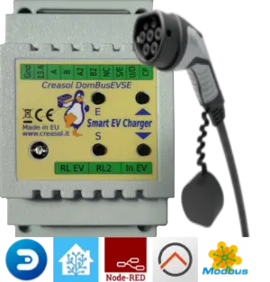
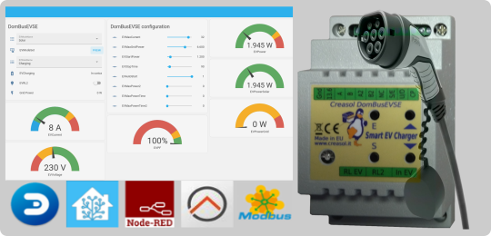
DomBusEVSE is a charging module available with 2 protocols:
- DomBus protocol (proprietary) with plugin for Domoticz and DomBusGateway python software that converts DomBus protocol in MQTT-AutoDiscovery, usable with Home Assistant, Node-RED, OpenHAB, ioBroker, ... In this case all entities are created automatically. Also, for HAOS or Home Assistant supervised, the DomBusGateway addon is available to communicate with all DomBus modules.
- Modbus protocol (standard) for Home Assistant, Node-RED, OpenHAB and other systems using Modbus RTU protocol, including custom magement programs.
It also works as stand-alone, in case that the domotic controller is off-line.
Hardware requirements to make a DIY EV charging station
Making a home-made charging station is quite simple, but needs to know about electric systems and power: charging sessions are usually long, so care must be taken to avoid overheating on connections and cables.
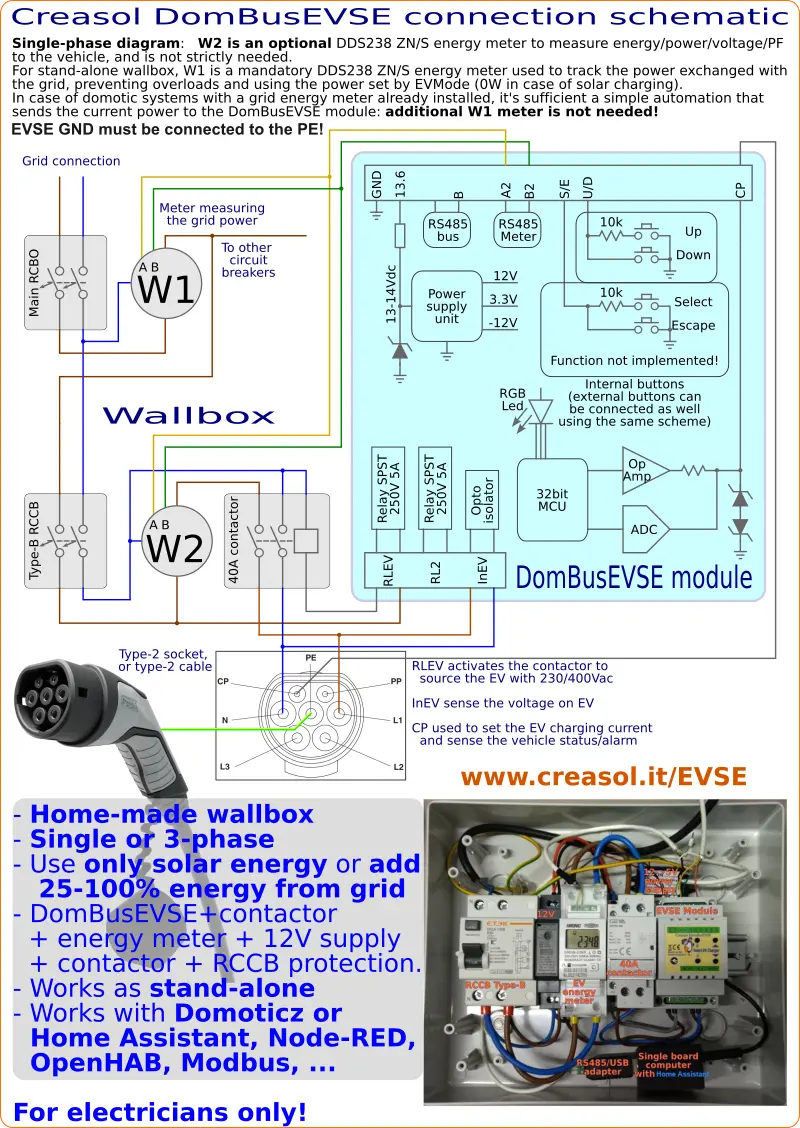
How does a EVSE module work? It measures the power drained from the electrical grid (or electrical grid - stationary battery power), sends to the car a PWM signal to set the maximum allowed charging power/current through the Control Pilot wire and read the vehicle status through the same wire.
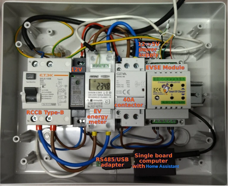
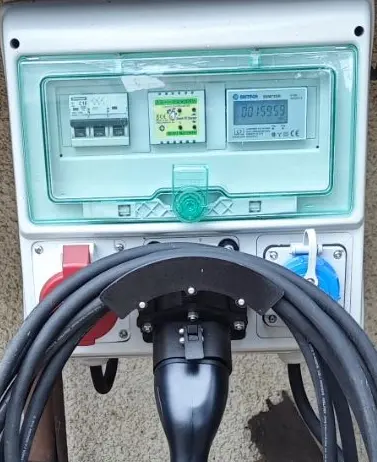
 The following items are needed to make a home-made charging station (with links with our store: they are standard devices so they may be purchased anywhere):
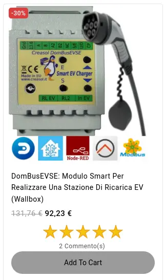
- DomBusEVSE, that is the charging controller
- Protections: type-B RCCB is recommended (2P for single-phase or 4P for three-phases)
- Contactor, to enable mains power supply (2P for single-phase or 4P for three-phases)
- EV cable, 32A for single phase, 16-32A for three-phase
- Power meter to measure the EV power, energy, voltage, power factor (optional but recommended)
- Bidirectional power meter to be placed in the main switchbox to measure the energy exchanged with the Grid
Two kits, with essential parts, are available in our store:
- Kit to make a homemade wallbox single phase
- Kit to make a homemade wallbox three phase
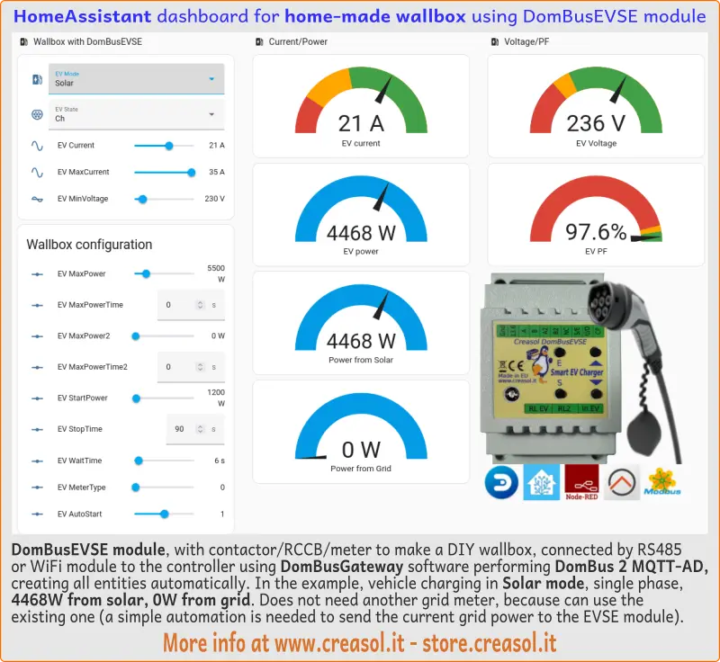
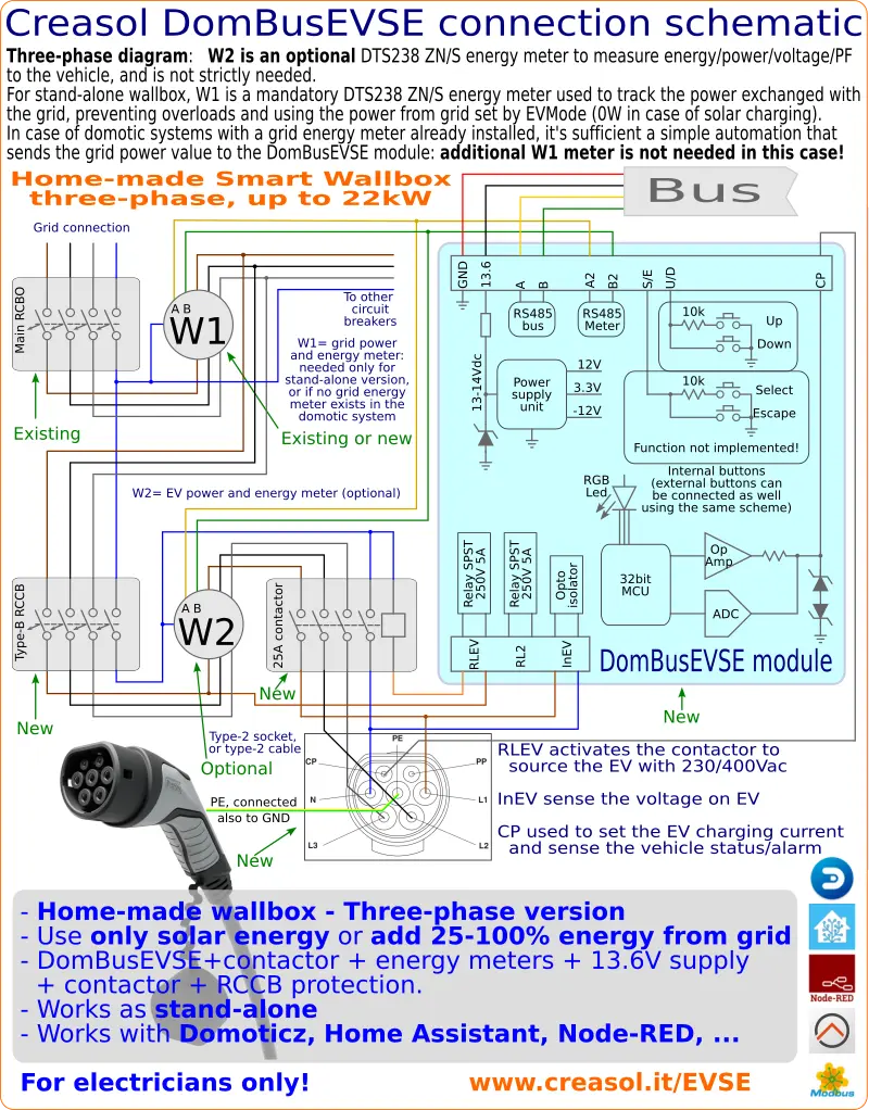
If a power meter to measure grid power is already available in the home automation system, or a solar inverter providing these data , you don't need to add a new one to make the wallbox: it's sufficient a simple automation that sends the grid power value to the DomBusEVSE module.
The power meter to measure EV voltage/power/energy/power factor/... is optional, but recommended. It can be connected to the DomBusEVSE port, or connected to the domotic controller as you prefer.
More info to make the wallbox are available in the DomBusEVSE page.
Do you need more support? Please visit:
For interactive support, contact us by Telegram or Whatsapp.
Integrating DomBusEVSE in Home Assistant using DomBus protocol
- Assure to purchase DomBusEVSE module with DomBus firmware.
- Intall DomBusGateway addon (for HAOS or Supervised HA) or DomBusGateway python software, providing a "DomBus to MQTT-AD" service
- Do all needed wirings to make your wallbox, connecting RCCB, optional energy meters (using DDS238 ZN/s for single phase, or DTS238 ZN/s for three phase), contactor, EV Cable, EVSE module, ... Power connections must be made with care, to prevent fire due to high current and dissipation, and with no voltage applied to prevent electric shocks! Assure that DomBusEVSE GND terminal block is also connected to protection earth (yellow/green cable).
Check this section to make a single phase charging station, and this section for a three phase charging station. - When EVSE is connected to the HA controller and is supplied, you should immediately see a new device, with address ffe3, within all entities for the charger.
Main entities can be accessed by MQTT, using the topic /dombus/BBHHHH_PPPP/state to get the current state, and /dombus/BBHHHH_PPPPP/set to set a new value, where BB=bus number, HHHH is the module address in hex format and PPPP is the port number, for example 01ffe3_0004 to access EV Mode port (4) for 0xffe3 module on bus 1:
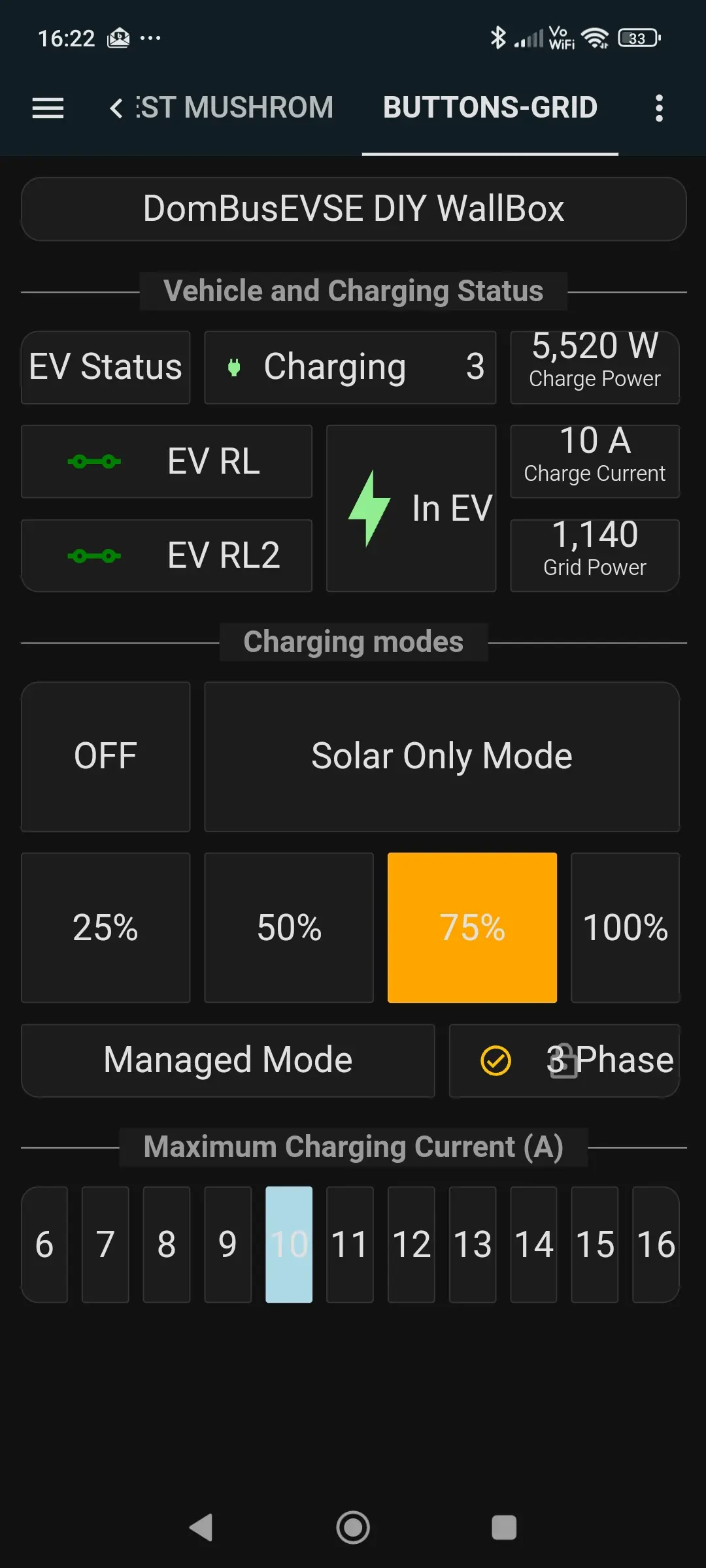
- EV Mode: it controls the EV charging and may be set to:
Off: charging disabled
Solar: use only power from photovoltaic / stationary battery (keeping grid power <= 0)
25%: use 25% of power from the grid (keeping grid power <= EV MaxPower * 0.25, for example, setting EV MaxPower = 6kW, the EVSE can use up to 1.5kW of power from grid
50%: use 50% of power from the grid (keeping grid power <= EV MaxPower * 0.5)
75%: use 75% of power from the grid (keeping grid power <= EV MaxPower * 0.75)
100%: use 100% of power from the grid (keeping grid power <= EV MaxPower)
Man: works in managed mode, where an automation provides the right value of EV Current to use for charging. This can be useful to manage several chargers distributing the power with an external algorithm among chargers.
In 100% mode it's also possible to maximize the charging power in this way: in Italy it's possible to use 110% of the contractual power forever, and 127% for no more than 90 minutes and no more than 50% duty cycle. So, having for example a contactual power of 6000W, it's possible to set EVMaxPower = 6600 , EVMaxPower2 = 7600, EVMaxPowerTime = 1200, EVMaxPowerTime2 = 1200 to get EVSE charging power, at 100%, by using 6600W for 20 minutes, followed by 7600W for another 20 minutes, then return back to 6600W for another 20 minutes, and so on. - EV State: shows the current vehicle status:
Off: unknown state
Disc: vehicle unplugged
Con: vehicle plugged
Ch: vehicle in charge
Vent: vehicle in charge, requesting ventilation
AEV: vehicle returned the ALARM state
APO: power outage error (no 230Vac sensed by In EV port)
AW: 230V sensed by In EV port even if contactor should be off: is contactor contact welded? - EV Current (range 6÷36): shows the value of current that the vehicle can drain, from 6 to EVMaxCurrent Ampere. Normally it's managed automatically by the EVSE microcontroller, depending by the EV Mode setting. It may be set by the user (or automation) when EV Mode is set to Man, as explained above.
- EV MaxCurrent (range: 6÷36): sets the max allowed current for charging, range from 6 to 32 Ampere.
- EV MinVoltage (range 0÷440): sets the minimum voltage to keep during charging session. It may use when the EV battery is almost full, to limit the charging current/power to the minimum needed to keep voltage below the setpoint. In Spring and Summer, for those who have a photovoltaic system, it may happen that grid voltage raises above 253V (in single phase) or 440V (three phase), causing overvoltage protection or inverter power derating, wasting energy (that the inverter cannot produce due to the overvoltage). To prevent overvoltage, it's possible to start EV charging, but to get a longer charging session expecially when the EV battery is almost full, it may be helpfully to set EV Mode = Solar and EV Minvoltage = 248V or 432V. To charge the vehicle at full speed, the EV MinVoltage should be set to 207 or 360 Volt. Video showing how this parameter works
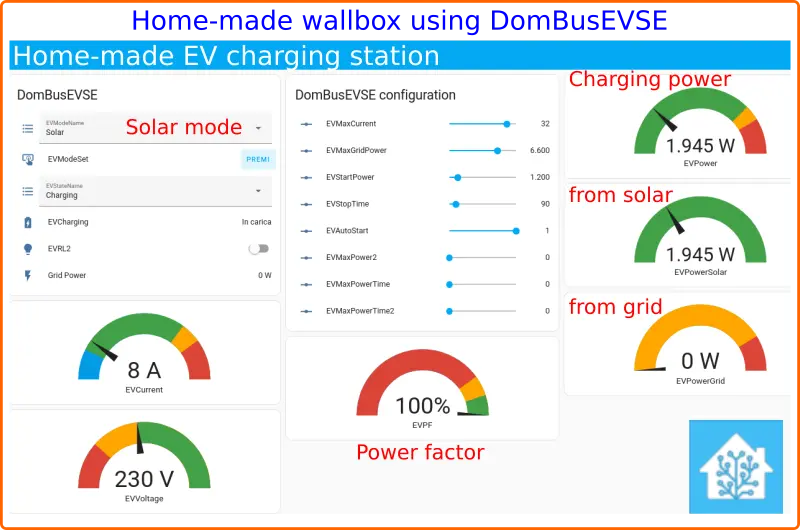
- EV Power: shows the power fed to the vehicle, sum of EV Power from Solar + EV Power from Grid
- EV Power from Solar: shows the power fed to the vehicle that comes from photovoltaic
- EV Power from Grid: shows the power fed to the vehicle that comes from electrical grid + stationary battery (if exists)
- EV Voltage: shows the charging voltage (before contactor)
- EV PF: show the power factor (may be much lower than 95% in case of charging with a low current => inefficient charge)
- Power from Grid: shows the actual power measured from the grid power meter. In case that the grid power meter is not connected directly to the EVSE module, an automation is needed to send the current power from Grid (negative if power is exported to the grid) to this entity. In case of hybrid solar inverter with stationary battery, it's possible to send the value power_from_grid - power_to_battery, so in Solar mode the EVSE will work to consume all available power from photovoltaic (no power from the grid and no power fo the stationary battery).
Integrating DomBusEVSE in Home Assistant using Modbus protocol
Install the Modbus integration .
Fetch the configuration files from the github page dedicated to DomBusEVSE and Home Assistant and put them into the HA config directory. You can see configuration files for different modules, so you have to enable what you need and disable the rest.
If you know English, please check this page in English language because other languages will be confused by the unnwanted translation of some parameters name.
Keep note that:
- this EVSE can be configured in "Managed mode" (an automation can periodically set the charging current value, from 6 to MAXCURRENT): in this way the EVSE become stupid and let the external automation to manage charging and balancing through different EVSE connected to the same electrical system.
- normally EVSE is not configured in "Managed mode", but can be configured in Off (don't charge), Solar (Grid power = 0), 25% (use Grid power = 25% of MAXPOWER), 50% (use 50% of MAXPOWER), 75% and 100% (use MAXPOWER from grid). To work correctly, you have to:
- connect a supported power meter (DDS238-2 ZN/S for single-phase, DTS238-4 ZN/S or DTS238-7 ZN/S for three-phase) programmed with slave-address=3 and connected to the additional Modbus port of the EVSE
- if you already have a power/energy meter connected to the domotic system, use a simple automation to write the current power (in Watt) drained from grid (negative if sourced to the grid) to the Grid Power entity. Example is available in the file dombus/dombusevse/dombusevse_automations.yaml The grid power should be written every 2-6s during charging session.


For additional support, enter the DomBus telegram group.
Single-phase homemade wallbox
Three-phase home-made smart wallbox
DIY wallbox made by SCiunczyk , with single-three phase switching capability, and WiFi/Modbus adapter
The project, using our EVSE module connected by WiFi/RS485 home-made converter using ESP32 + ESPHome firmware, is described in the GitHub page https://github.com/SCiunczyk/wallbox-diy and permits to charge an electric vehicle by using single-phase (low power, from 1kW to 7kW, generally used in Solar mode) and three-phase power (used to charge the vehicle at full speed, from 4kW to 22kW).
Thanks to Slawomir for sharing info about his very smart wallbox!
More info at https://www.creasol.it/EVSE