")
")
")
")
")
")
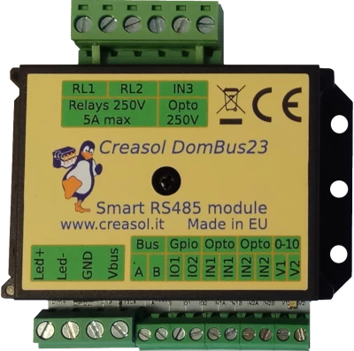
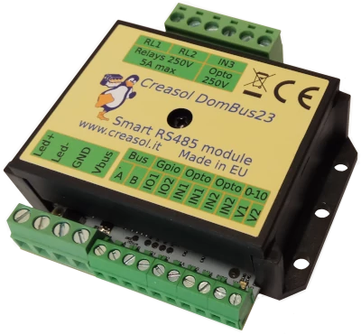
Creasol DomBus23 is a module for home automation system with several different kind of configurable inputs/outputs in a short size: 74x72x24mm.
It can be connected to the home automation controller by a RS485 serial bus (4 wires, 2 for 12/24V power supply, and 2 for data at 115200bps).
Supported home automation system controllers are Domoticz .
As other DomBus devices, DomBus23 is designed to consume low power, be reliable, fully configurable and easy to use.
Features
- 2x SPST relay outputs, 250Vac 5A, that can be configured in low power mode to minimize power consumption (less than 70mW/relay, instead of 200mW/relay) and in OUT_BLIND mode to drive a roller shutter motor
- 1x mosfet output, 30V 10A max, with both digital and dimmer functions, that can be used to drive led stripe regulating the brightness
- 2x 0-10V analog output (can be used to control other electronic boards with 0-10V input, like dimmers): each one can be configured as open-drain output (available through the optional cable) in case that 0-10V analog output is useless
- 2x I/O lines, each one can be configured as digital input, analog input, twinbutton, counter (for energy gas or water meters), alarm sensor (magnetic, PIR, double-biased and triple-biased balanced alarm sensors), digital output, blind, dimmer (to be connected to external mosfet) and buzzer (piezo buzzer connected to the two lines, in push-pull configuration). Each port has two PCB jumper: one to reduce serie resistance to 150ohm, useful when it's configured as output or buzzer, and one to enable a fixed 10k pull-up resistor, needed when port is configured as twinbutton.
- 2x low voltage AC/DC opto-isolated inputs, 9-40V
- 1x 230V AC opto-isolated input
- 7.5-35Vdc power supply (internally regulated by a switching mode power supply circuitry that minimize power consumption and dissipation)
- low power consumption: 10mW stand-by power
- 115200 bps RS485 bus (max length: 1km)
Warnings
- Do not mix high voltage (230V) loads and low voltage (5/12/24V) loads on the same terminal block! In case that IN3 is used to monitor 230V voltage, RL1 and RL2 can be use ONLY to control 230V loads. Also, it's not possible to use a relay to control 230V load and another one to control a low voltage load!
- Use a 4 wires shielded cable for the bus, using two lines to send power supply (12 or 24Vdc) protected by a fuse.
- To reduce noise and reflections on the bus, enable the termination resistor (shorting Rbus PCB jumper) on the two furthest ends of the bus.
{youtube}-oDiKHSg6kM{/youtube}
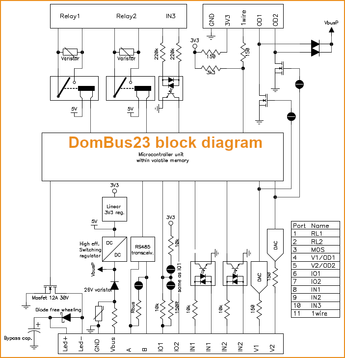
DomBus23 Ports capabilities
Default address: 0xff23
| Port# | Name | Capabilities | Default configuration | Description |
| 1 | RL1 | OUT_DIGITAL, OUT_RELAY_LP, OUT_BLIND | OUT_RELAY_LP | SPST relay output, with 250Vac 5A contact rate, or 30Vdc 5A contact rate. Relay contact is protected from overvoltage by varistor |
| 2 | RL2 | OUT_DIGITAL, OUT_RELAY_LP, OUT_BLIND | OUT_RELAY_LP | SPST relay output, with 250Vac 5A contact rate, or 30Vdc 5A contact rate. Relay contact is protected from overvoltage by varistor |
| 3 | MOS | OUT_DIGITAL, OUT_DIMMER | OUT_DIMMER | Mosfet open-drain output, 30V 12A max, suitable to control led stripes (with the possibility to regulate the brightness using the DomBus dimming function, 0-100% with 5% step) or other DC loads. |
| 4 | V1/OD1 | OUT_ANALOG, OUT_DIGITAL, OUT_RELAY_LP, OUT_BLIND | OUT_ANALOG |
Analog output, 0-10V, suitable to control the 0-10V or 1-10V input of another electronic board (dimmer, heat pump, linear valve, ...). |
| 5 | V2/OD2 | OUT_ANALOG, OUT_DIGITAL, OUT_RELAY_LP, OUT_BLIND(1) | OUT_ANALOG | OAnalog output, 0-10V, suitable to control the 0-10V or 1-10V input of another electronic board (dimmer, heat pump, linear valve, ...). Optionally it's possible to configure this port as open-drain output 40V 100mA max, that can be connected to external leds or relay by using the optional 5-wires cable: od2 pcb jumper must be shorted, in this case. |
| 6 | IO1 | IN_DIGITAL, IN_ANALOG, IN_TWINBUTTON, IN_COUNTER, OUT_DIGITAL, OUT_BLIND, OUT_DIMMER, OUT_BUZZER, SENSOR_ALARM | IN_DIGITAL |
Analog/digital input that can be used to read voltages, or can be connected to contact, switch, magnetic sensor, PIR, ... |
| 7 | IO2 | IN_DIGITAL, IN_ANALOG, IN_TWINBUTTON, IN_COUNTER, OUT_DIGITAL, OUT_BLIND(1), OUT_DIMMER, OUT_BUZZER, SENSOR_ALARM | IN_DIGITAL | Analog/digital input that can be used to read voltages, or can be connected to contact, switch, magnetic sensor, PIR, ... It can be configured as counter and connected to energy/gas/water meter. It can be configured as IN_TWINBUTTON (that can be connected to a double pushbutton) by shorting the PCB jumper RU2, or 10mA OUTPUT by shorting the PCB jumper RO2: in the latter case, it can be used as a low current 3V output, connected to buzzer or to a relay board within the coil driver. Enabling the internal pullup RU2, can be used also for NTC thermistor. It also can be connected to a balanced double-biased or triple-biased alarm sensor that, with 2 wires (GND+IOx) can get 5 states: Closed, Open, Masked, Tamper, Shorted. |
| 8 | IN1 | IN_AC | IN_AC, IN_COUNTER | Low voltage input, 9-40V AC or DC, opto-isolated. Suitable to sense the presence of voltage |
| 9 | IN2 | IN_AC | IN_AC, IN_COUNTER | Low voltage input, 9-40V AC or DC, opto-isolated. Suitable to sense the presence of voltage |
| 10 | IN3 | IN_AC | IN_AC, IN_COUNTER | 230V input, opto-isolated. Suitable to sense the presence of voltage, and detect power-outage (blackout) |
(1): can be used as BLIND output, to open a blind/curtain, but only the previous port can be configured in Domoticz as OUT_BLIND because, when configured as OUT_BLIND, DomBus device automatically configure the next port to drive a relay in open direction.
DomBus23 Modbus RTU capabilities (for the Modbus version)
At power-on, the module shows on red/blue LED the current Modbus slave address (register address=8192) in decimal format, on green LED the serial baudrate (reg. 8193), and finally on red/blue LED the serial parity (reg. 8194).
If a value is zero, a long flash is emitted.
For example, if reg(8192)=35, reg(8193)=0, reg(8194)=0, at power the following led flashes will be shown:
3 red/blue flashes, pause, 5 red/blue flashes (slave address= 0x23 = 35), pause, 1 long green flash (reg(8193)=0 => baudrate=115200bps), pause, 1 long red/blue flash (reg(8194)=0 => parity=None).
Device will be operative only when address/baudrate/parity parameters have been shown: then module will accept commands by Modbus RTU, and periodically shows output status for all ports, from 1 to max port: green flash means that port status is Off, red/blue flash means that port is On.
Default slave address: 35 (0x23)
| Addr | Name | Values | Description |
| 0 | RL1 | 0=OFF, 1 or 65280=ON, 2-65279=ON for specified time.Logic can be inverted specifying the INVERTED option (on address 512+port) | SPST relay output, NO contact, 5A 250Vac or 30Vdc output capability. Relay contact is protected by varistor. |
| 1 | RL2 | 0=OFF, 1 or 65280=ON, 2-65279=ON for specified time.Logic can be inverted specifying the INVERTED option (on address 512+port) | SPST relay output, NO contact, 5A 250Vac or 30Vdc output capability. Relay contact is protected by varistor. |
| 2 | MOS |
0=Mosfet OFF |
Mosfet open-drain output, 30V 12A max, suitable to control led stripes (with the possibility to regulate the brightness using the DomBus dimming function, 0-100% with 5% step) or other DC loads. |
| 3 | V1/OD1 | 0-10V Analog output: 0=0V, 100=10V 1%, step=0.1V OpenDrain output: 0=OFF, 1=ON, 2-65279=ON for the specified time |
Analog output, 0-10V, suitable to control the 0-10V or 1-10V input of another electronic board (dimmer, heat pump, linear valve, ...). Optionally it's possible to configure this port as open-drain output 40V 100mA max, that can be connected to external leds or relay by using the optional 5-wires cable: od1 pcb jumper must be shorted, in this case. |
| 4 | V2/OD2 | 0-10V Analog output: 0=0V, 100=10V 1%, step=0.1V OpenDrain output: 0=OFF, 1=ON, 2-65279=ON for the specified time |
Analog output, 0-10V, suitable to control the 0-10V or 1-10V input of another electronic board (dimmer, heat pump, linear valve, ...). Optionally it's possible to configure this port as open-drain output 40V 100mA max, that can be connected to external leds or relay by using the optional 5-wires cable: od2 pcb jumper must be shorted, in this case. |
| 5 | IO1 |
0=OFF (input externally pulled/shorted to GND), 1=ON (input externally disconnected, with internal pullup to 3.3V). Logic can be inverted with the INVERTED option (to be set on address 512+port). If configured as SENSOR_ALARM, 5 values can be assumed: 0=Closed, 1=Open, 2=Masked zone, 3=Tamper, 4=Short circuit. |
Digital input, with internal pullup. Can be configured as digital input with internal pulldown, analog input, NTC temperature sensor input, twinbutton, digital output, buzzer output, distance sensor by setting the register 256+port. On the PCB it's possible to enable ROx PCB jumper to get a lower output impedance (150 Ohm instead of 10k) and RUx PCB jumper to enable 10k pullup (used for NTC and twinbutton). |
| 6 | IO2 |
0=OFF (input externally pulled/shorted to GND), 1=ON (input externally disconnected, with internal pullup to 3.3V). Logic can be inverted with the INVERTED option (to be set on address 512+port). If configured as SENSOR_ALARM, 5 values can be assumed: 0=Closed, 1=Open, 2=Masked zone, 3=Tamper, 4=Short circuit. |
Digital input, with internal pullup. Can be configured as digital input with internal pulldown, analog input, NTC temperature sensor input, twinbutton, digital output, buzzer output, distance sensor by setting the register 256+port. On the PCB it's possible to enable ROx PCB jumper to get a lower output impedance (150 Ohm instead of 10k) and RUx PCB jumper to enable 10k pullup (used for NTC and twinbutton). |
| 7 | IN1 | 0=OFF (no voltage applied to optoisolator). 1=ON (voltage applied to optoisolator). |
Low voltage opto-isolated input, 9-40V AC or DC. Suitable to sense the presence of voltage |
| 8 | IN2 | 0=OFF (no voltage applied to optoisolator). 1=ON (voltage applied to optoisolator). |
Low voltage opto-isolated input, 9-40V AC or DC. Suitable to sense the presence of voltage |
| 9 | IN3 | 0=OFF (no voltage applied to optoisolator). 1=ON (voltage applied to optoisolator). |
230V input, opto-isolated. Suitable to sense the presence of voltage, and detect power-outage (blackout) |
| 256-267 | Port config | 1=OUT_DIGITAL, 2=OUT_RELAY_LP, ... |
Command used to configure port 1 (256), port 2 (257), ... as OUT_DIGITAL or OUT_RELAY_LP (low power consumption relay) or other value (see table below) |
| 512-523 | Port option | 0=NORMAL, 1=INVERTED (output normally ON, or input is ON when port voltage is 0V) | Set port option. If set to 1, output stays ON after boot until the port is asserted (then relays goes OFF). For inputs, setting INVERTED the port value is ON (1) when input voltage is 0V, OFF when input is left open with internal pullhigh enabled. |
| 8192 | Slave Address | 1-247 | Permits to change the slave address of the module, so it's possible to add other modules to the same bus |
| 8193 | Serial bitrate | 0=115200bps, 1=57600, 2=38400, 3=19200, 4=9600, 5=4800, 6=2400, 7=1200bps | Serial speed, default 115200 bps 8,n,1 |
| 8194 | Serial parity | 0=None, 1=Even, 2=Odd | Serial parity, default none (115200 bps 8,n,1) |
| 8198 | Revision, major | Read only | Get firmware version, major number. For example "02" means that revision is "02XX" where XX defined by parameter 8199 |
| 8199 | Revision, minor | Read only | Get firmware version, minor number. For example "h1" means that revision is "XXh1" where XX defined by parameter 8198 |
It's possible to activate one or more outputs for a certain amount of time (monostable/timer output) as indicated in the table. The parameter corresponding to the needed time can be computed using the following rules:
From 0 to 60s => 31.25ms resolution 2=62.5ms, 3=93.75ms, ... 1920=60s => value=time_in_milliseconds/31.5
From 1m to 1h with 1s resolution 1921=61s, 3540+1920=5460=1h => value=(time_in_seconds-60)+1920
From 1h to 1d with 1m resolution 5461=1h+1m, 1380+5460=6840=24h => value=(time_in_minutes-60)+5460
From 1d to 1500 days with 1h resolution 6841=25h, 6842=26h, and so on => value=(time_in_hours-24)+6840
The following tables show some Modbus commands examples.
| Slave Addr | Func. Code | Reg.Addr | Reg.Value | Frame | Description |
| 35 | 06 | 8192 | 1 | [23][06][20][00][00][01][xx][xx] | Change slave address from 35 (0x23 in hex format) to 1 |
| 01 | 06 | 8193 | 4 | [01][06][20][01][00][04][D2][09] | Set serial speed to 9600bps |
| 01 | 06 | 8194 | 1 | [01][06][20][02][00][01][E2][0A] | Set even parity |
| 49 | 10 | 8192 | 1,4,1 | [31][10][20][00][00][03][06][00][01][00][04][00][01][B1][71] | With a single command, set slave address to 1, serial speed to 9600bps, even parity. Original modules address was 49 (0x31) in this example. |
| 01 | 06 | 0 | 65280 | [01][06][00][00][FF][00][C8][3A] | Activate RL1 output forever (65280=0xff00) |
| 01 | 06 | 1 | 960 | [01][06][00][01][03][C0][D8][AA] | Activate RL2 for 960/32=30s |
| 01 | 10 | 0 | 32,0,0,65280 | [31][10][00][00][00][04][08][00][20][00][00][00][00][FF][00][E6][5C] | Set RL1 On for 1s (32), RL2 Off, RL3 Off, RL4 On - Max 10 registers can be set in one command |
| 01 | 03 | 8198 | 2 | [01][03][20][06][00][02][2F][CA] | Read 4 bytes within module version. For example, if returned value is <30><32><68><31> (in hex format), the corresponding ASCII value is "02h1" (Firmware 02h1) |
| 01 | 0F | 0 | 8,1,0xd1 | [01][0F][00][00][00][08][01][D1][3E][C9] | Set coil status to 0xd1 (0b11010001), activating RL8, RL7, RL5, RL1 and disabling other relays |
| 01 | 01 | 0 | 8 | [01][01][00][00][00][08][3D][CC] | Read coil status. If returned value is 0xd1 (0b11010001), it means that RL8, RL7, RL5 and RL1 are On |
Modbus protocol can be tested easily using a modbus program, like mbpoll for Linux:
mbpoll -v -m rtu -0 -1 -a1 -b115200 -Pnone -r 0 /dev/ttyUSB0 32 0 64 128 0 0 0 65280
to activate RL1 for 1s, R3 for 2s, RL4 for 4s and RL8 forever.
mbpoll -v -m rtu -0 -1 -a1 -b115200 -Pnone -r 255 -c 1 /dev/ttyUSB0
to read all port states.
Application notes
Dimming 1 led stripe by internal Mosfet 24V 12A, + 2 led stripes using external controller
DomBus23 module can be interface with Domoticz and, using the internal mosfet with 30V 12A, can internally regulate the brightness of a led stripe.
Also, DomBus23 has 2 analog outputs 0-10V that permit to control 2 additional led stripes by an external led dimmer.

Connecting DomBus23 to the gate or garage door opener, to open gate /garage door by Domoticz
The following schema shows how to connect the gate opener or garage door opener to DomBus23 module, that permit to control gate and garage door by home automation system (Domoticz, ...)
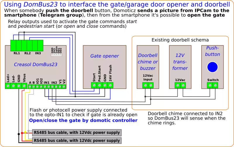
Converting a simple door bell to a smart doorbell for Domoticz
The following schema can be used to convert an existing "analog" doorbell to a smart doorbell.
The 12Vac used to supply the door bell chime or buzzer is connected to an optoisolated input on the DomBus23 module, so when the chime/buzzer is supplied, a trigger is sent to Domoticz that activates a script to grab a picture from the IPcam and send it to a Telegram channel or group, so the family members can receive the photo on their smartphones as soon as someone push the doorbell button.
A complete description is available at the following article while the updated scripts for Domoticz are available on GitHub.
DomBus23 has many inputs and outputs and can be used to performs other functions, such as opening a pedestrian gate or main door (it has 2 relay outputs), manage a courtesy light with led stripe with dimming function (it has a 30V 12A mosfet), ....
If the doorbell uses 230Vac or 110Vac power, it's possible to connect the chime/buzzer to the IN3 optoisolated input, that supports high voltages.

Connecting Eastron SDM230 to DomBus23 to measure import and export energy/power on Domoticz
 Many energy meters, like Eastron SDM230, provide 2 pulse outputs to count the import and export energy, 1 pulse every Wh (1000 pulses per kWh).
Using DomBus12, DomBus23 or DomBusTH it's very easy to read the pulses from energy meters, compute the instant power and get two devices in Domoticz that show the usage and return power, usage and return total energy and graphs. Below the instructions that refer to Eastron SDM230 energy meter: similar procedure for any other energy meter with pulse outputs.
- connect the pulse outputs to the DomBus23 IO1 and IO2. The SDM230 common terminal block should be connected to GND (0V).
- configure Pulse1 output, on SDM230, as EXP kWh (check the manual to know how to do that); Pulse2 is pre-configured as IMP kWh (measure the energy imported from grid)
- configure the Domoticz device connected to Pulse2: press Edit on that device, and replace in the Description field IN_DIGITAL or IN_TWINBUTTON (the default value) with IN_COUNTER,TYPENAME=kWh and save. Please note that kWh is CASE SENSITIVE!
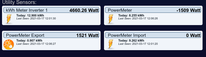
Now the device will be automatically moved to the Utility panel and configured as energy meter. Edit it again, write a name (for example PowerMeter_Import), and select Usage type. - if p
![Energy Power Meter Devices in Domoticz]() roduced energy should be measured, configure the Domoticz device connected to Pulse1 as before: press Edit on that device, and replace in the Description field IN_DIGITAL or IN_TWINBUTTON with IN_COUNTER,TYPENAME=kWh and save.
roduced energy should be measured, configure the Domoticz device connected to Pulse1 as before: press Edit on that device, and replace in the Description field IN_DIGITAL or IN_TWINBUTTON with IN_COUNTER,TYPENAME=kWh and save.
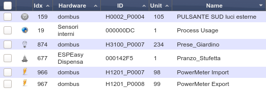
Now the device will be automatically moved to the Utility panel and configured as energy meter. Edit it again, write a name (for example PowerMeter_Export), and select Return type. - In case of both import and export devices are created, it's needed to specify on Import device the Unit number of the Export device, and vice versa. So, select Setup -> Devices and write down the Unit number corresponding to Import (for example 98), and Export device (for example 99), then go to Utility panel, edit Import device and add to the description ,OPPOSITE=99 (Unit of the Export device) and save; edit Export device and add to the description ,OPPOSITE=98 (Unit of the Import device) and save. In this way, when a pulse is received on Import device, the power on Export device will be immediately set to 0, and vice versa, when a pulse is received on Export device, the power on Import device will be set to 0.
 roduced energy should be measured, configure the Domoticz device connected to Pulse1 as before: press Edit on that device, and replace in the Description field IN_DIGITAL or IN_TWINBUTTON with IN_COUNTER,TYPENAME=kWh and save.
Domoticz needs up to 5 minutes before updating the energy counter correctly.
Domoticz script the script_device_power
Installing the files script_device_power.lua and config_power.lua provided on GitHub into the scripts/lua directory of Domoticz, it's possible to add the following functions to Domoticz:
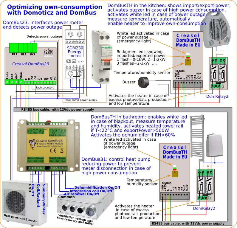
- power outage detect => turns on Leds (and other devices) in case of blackout (power failure)
- import and export power displaying, through red/green leds on DomBusTH (red led flashes 1 time if import power <1kW, 2 times if <2kW, ... green led flashes 1 time if export power <1kW, 2 times if power < 2kW, ....)
- in case of high power usage, program heat pump to work at lower level, or disconnect loads to prevent power disconnect. In case there are not any load that can be disconnect, send alert through leds/buzzer/siren, and send alert by Telegram
- automatically enable loads in case of extra power from renewable sources, to increase the own-consuming: for example activate an electric heater if temperature is below a level and available power is greater than heater power
#from linux shell, type the following commands (copy and paste): lines starting with # are comments, and can be ignored
#become root
sudo su -
#enter domoticz directory /scripts/lua
cd ~pi/Domoticz/scripts/lua
if [ -d domoticz_lua_scripts ]; then
  cd domoticz_lua_scripts
  #update domoticz_lua_script local repository
  git pull
  cd ..
else
  which git
  if [ $? -ne 0 ]; then
    #install git
    apt install git
  fi
  #download domoticz_lua_scripts repository with all scripts
  git clone https://github.com/CreasolTech/domoticz_lua_scripts.git
fi
cp -i domoticz_lua_scripts/script_device_power.lua domoticz_lua_scripts/config_power.lua .
#now edit config file
nano config_power.lu
and adjust the information in the configuration file to match your home automation system.