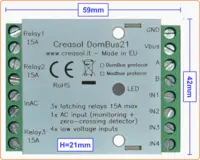
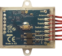
DomBus32 is a DIN-RAIL module, 54mm wide, with 3 relay outputs, 3 AC inputs and 5 low-voltage I/Os.
AVAILABLE IN TWO VERSIONS: DomBus protocol and Modbus protocol!
The English language page contains the updated information
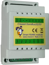
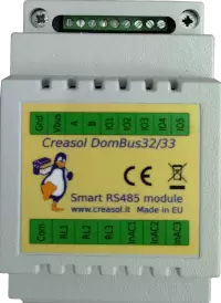
To simplify wiring, the terminal block has 3 terminals for relays, 3 for AC inputs, and 1 common terminal (to be connected to Neutral or Line): in this way it's easier and faster to connect the module to electrical loads sharing the same circuit breaker (e.g. light system, heating system valves, ...). Please take care to connect only loads that are protected by the same RCCB (circuit breaker). Of course it's possible to use relays to switch low voltage loads or select the working mode of a machine (heat pump, for example), connecting the common line to GND or DC supply voltage: in this case the 3 AC inputs are useless.
As other DomBus modules, all ports can be configured in many different ways, and also this module supports DCMD, commands sent to the same or other DomBus modules to perform simple actions, that permit to achieve high reliability (DCMD commands work even if domotic controller is not operational) and easy programming (don't need to create automations in the home automation controller: just configure DomBus ports to perform actions on events). DCMD also permits to activate a Domoticz group or scene when an event occurr, for example a pushbutton switch has been pushed (pulse 500ms, pulse 1s, pulse 2s, pulse 4s), a sensor reached a value, ...
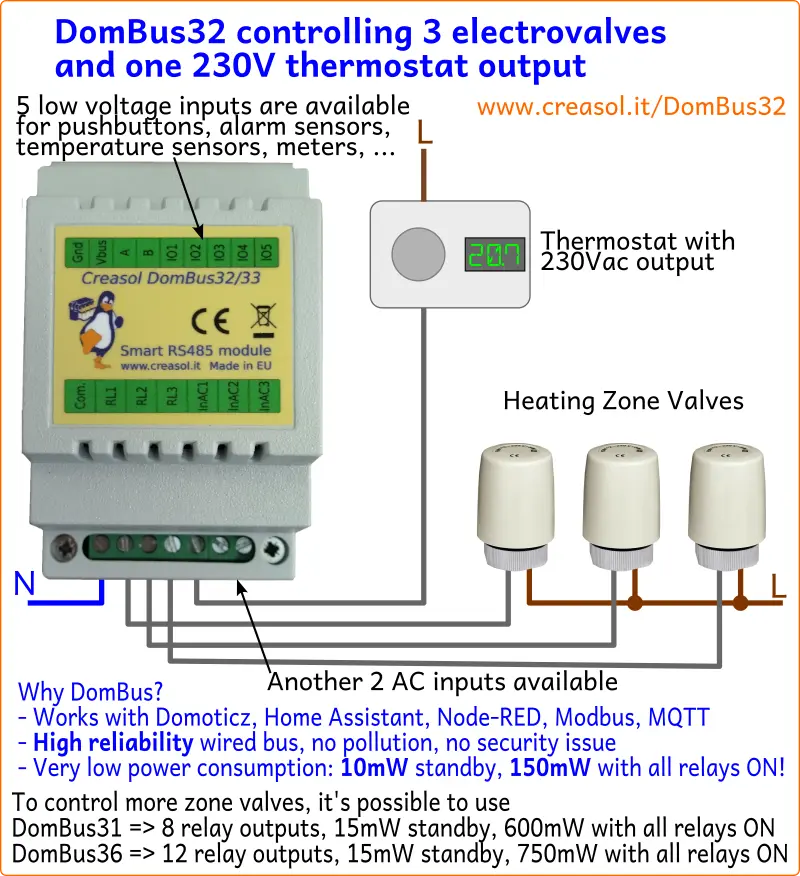
Last, but not least, as other DomBus modules, DomBus32 is optimized to get low power consumption, less than 10mW normally (0.75mA @13.6V) and less than 150mW when all 3 relays are ON (10mA @13.6V).
It's available with two firmware types: DomBus (proprietary protocol with enhanced features) for Domoticz controller, and Modbus RTU (standard protocol working with almost any home automation system). Check below for a detailed comparison between the two protocols.
It uses a RS485 industrial-grade serial bus, using a common shielded cable with 4 wires: 2 for 12/24V power supply, and 2 for data at 115200bps 8,n,1 (or other speed/parity in case of Modbus RTU).
It supports two different protocols (at puchase time, select the needed protocol!):
- DomBus protocol, that is supported by Domoticz home automation controller, is a reliable multi-master protocol that permits to manage dozens of modules and get status from a module as soon as it changes. Also it includes the so-called DCMD commands that, similarly to KNX, are transmitted between DomBus modules in the same bus to activate outputs, scenes and groups in case of events without needing for the intervention of the home automation controller, useful solution to get a home automation system working even in case of domotic controller fault. Check below for an explanation about DCMD.
The Creasol DomBus plugin have to be installed in Domoticz, using the Python Plugin Manager or downloading the software from GitHub (see the section below). - Modbus RTU protocol, widely used in industrial and home automation systems, is supported by almost any domotic controller like Home Assistant, OpenHAB, IObroker, Node-RED, ...
Modbus is a master-slave protocol that permits to activate and deactivate a single relay or a group of relays by a single command. Also, it's possible to specify, for each relay, the ON time from 31.5ms to 1500 days, so the relay automatically switches OFF after the selected time.
Confused about the two versions? If you use Domoticz, DomBus version is much better because includes enhanced features like DCMD and devices autodiscovery. For other building automations, Modbus version should be chosen because compatible with almost everything.
Ask for support on Telegram group https://t.me/DomBus
The RS485 serial bus is the ideal solution to get:
- easy wiring and connection: use a common thin alarm cable within 4 wires, 2x0.5mm² wires for 12V power supply, and 2x0.22mm² wires for data. This is much easier and better than ethernet UTP/STP connections.
- robustness differential signalling permits to connect about 30 modules with more than 200m total distance. Modules can be connected together using a mix of linear/star bus topology.
- very low power consumption: each module is supplied at 12V and has inside an high efficiency switching mode converter to minimize the power comsumption.
- power outage tolerant: using a 13.6V power supply with lead acid battery it's possible to supply domotic network, IPCams, NVR, switches, routers, so the system keeps working even in case of power cut-out.
- no RF pollution, no batteries to change
For large building, to improve the bus reliability, it's possible to make more than 1 bus so in case of fault, only the bus with fault stops working.
Features
- 3 relay outputs, 250Vac 5A max, with overvoltage protection (varistors)
- 3 AC inputs, 110-230V, to monitor voltage on loads
- 1 common terminal block (for Neutral, Line or common voltage), to simplify connections
- 5 programmable low-voltage I/Os
- DCMD supports (DomBus firmware only): this is a feature (described below) that permits to get easy automations without writing a line of code, and command exchanged between DomBus modules even in case that domotic controller is stopped. For example configuring a pushbutton input port as
DCMD(Pulse)=11.3:Toggle, DCMD(Pulse1)=0.7:Toggle, DCMD(Pulse2)=0.8:On
it's possible:
* with a short 0.5s pulse, toggles on/off port #3 output of DomBus module #11
* with a 1s pulse, toggle on/off a group of switches on the controller
* with a 2s long pulse, activate a scene that, for example, disable all lights/loads and activate the alarm system (useful when leaving the building). - 8-25Vdc power supply
- 10mW power consumption, 150mW max power consumption with all relays ON
- 53x89x65mm
Applications
- Turn on/off up to 3 lights or other loads
- Check that appliances are supplied (e.g. check that Heat Pump is correctly supplied during the winter, to prevent that idraulic circuit breaks during the Winter when temperature falls below 0°C)
- Turn on/off heating system valves
- Connect external pushbutton switches, switches, double pushbuttons, S0 counters, ....
- Connect up to 5 PIRs, magnetic contact sensors, or other low voltage devices.
- Interface up to 3 PIRs with 230V output to enable external lights and start recording (NVR or DVR)
- ....
Warnings
- Do not mix high voltage (230V) loads and low voltage (5/12/24V) loads on the same terminal block!
- Use a 4 wires shielded cable for the bus (common alarm cable, 2x0.5mm² + 2x0.22mm²), using two lines to feed power supply (12 or 24Vdc) protected by a fuse.
- To reduce noise and reflections on the bus, enable the termination resistor (shorting Rbus PCB jumper) on the two furthest ends of the bus.
DomBus32 Ports capabilities
Default address: 0xff32
Port# | Name | Capabilities | Default configuration | Description |
1 | RL1 | OUT_DIGITAL, OUT_RELAY_LP | OUT_RELAY_LP | SPST relay output, with 250Vac 5A contact rate, or 30Vdc 5A contact rate. Relay contact is protected from overvoltage by varistor. 1 common terminal (Neutral, Line, positive voltage or ground) for all relays and AC inputs |
2 | RL2 | OUT_DIGITAL, OUT_RELAY_LP | OUT_RELAY_LP | SPST relay output, with 250Vac 5A contact rate, or 30Vdc 5A contact rate. Relay contact is protected from overvoltage by varistor. 1 common terminal (Neutral, Line, positive voltage or ground) for all relays and AC inputs |
3 | RL3 | OUT_DIGITAL, OUT_RELAY_LP | OUT_RELAY_LP |
SPST relay output, with 250Vac 5A contact rate, or 30Vdc 5A contact rate. Relay contact is protected from overvoltage by varistor. 1 common terminal (Neutral, Line, positive voltage or ground) for all relays and AC inputs |
4 | InAC1 | IN_AC, IN_COUNTER | IN_AC | 100-250Vac input, opto-isolated, suitable to sense the presence of voltage. 1 common terminal (Neutral or Line) shared with all AC inputs and relays. |
5 | InAC2 | IN_AC, IN_COUNTER | IN_AC | 100-250Vac input, opto-isolated, suitable to sense the presence of voltage. 1 common terminal (Neutral or Line) shared with all AC inputs and relays. |
6 | InAC3 | IN_AC, IN_COUNTER | IN_AC |
100-250Vac input, opto-isolated, suitable to sense the presence of voltage. 1 common terminal (Neutral or Line) shared with all AC inputs and relays. |
7 | IO1 | IN_DIGITAL, IN_TWINBUTTON, IN_COUNTER, OUT_DIGITAL, OUT_DIMMER, OUT_BUZZER | IN_DIGITAL,INVERTED | Analog/digital input that can be used to read voltages, or can be connected to contact, switch, magnetic sensor, PIR, ... It can be configured as counter and connected to energy/gas/water meter. It can be configured as IN_TWINBUTTON (that can be connected to a double pushbutton) by shorting the PCB jumper PU1, or 10mA OUTPUT by shorting the PCB jumper RO1: in the latter case, it can be used as a low current 3V output, connected to buzzer or to a relay board within the coil driver. Enabling the internal pullup PU1, can be used also for NTC thermistor. |
8 | IO2 | IN_DIGITAL, IN_TWINBUTTON, IN_COUNTER, OUT_DIGITAL, OUT_DIMMER, OUT_BUZZER | IN_DIGITAL,INVERTED | Analog/digital input that can be used to read voltages, or can be connected to contact, switch, magnetic sensor, PIR, ... It can be configured as counter and connected to energy/gas/water meter. It can be configured as IN_TWINBUTTON (that can be connected to a double pushbutton) by shorting the PCB jumper PU2, or 10mA OUTPUT by shorting the PCB jumper RO2: in the latter case, it can be used as a low current 3V output, connected to buzzer or to a relay board within the coil driver. Enabling the internal pullup PU2, can be used also for NTC thermistor. |
9 | IO3 | IN_DIGITAL, IN_TWINBUTTON, IN_COUNTER, OUT_DIGITAL, OUT_DIMMER, OUT_BUZZER | IN_DIGITAL,INVERTED | Analog/digital input that can be used to read voltages, or can be connected to contact, switch, magnetic sensor, PIR, ... It can be configured as counter and connected to energy/gas/water meter. It can be configured as IN_TWINBUTTON (that can be connected to a double pushbutton) by shorting the PCB jumper PU3, or 10mA OUTPUT by shorting the PCB jumper RO3: in the latter case, it can be used as a low current 3V output, connected to buzzer or to a relay board within the coil driver. Enabling the internal pullup PU3, can be used also for NTC thermistor. |
10 | IO4 | IN_DIGITAL, IN_TWINBUTTON, IN_COUNTER, OUT_DIGITAL, OUT_DIMMER, OUT_BUZZER | IN_DIGITAL,INVERTED | Analog/digital input that can be used to read voltages, or can be connected to contact, switch, magnetic sensor, PIR, ... It can be configured as counter and connected to energy/gas/water meter. It can be configured as IN_TWINBUTTON (that can be connected to a double pushbutton) by shorting the PCB jumper PU4, or 10mA OUTPUT by shorting the PCB jumper RO4: in the latter case, it can be used as a low current 3V output, connected to buzzer or to a relay board within the coil driver. Enabling the internal pullup PU4, can be used also for NTC thermistor. |
11 | IO5 | IN_DIGITAL, IN_TWINBUTTON, IN_COUNTER, OUT_DIGITAL, OUT_DIMMER, OUT_BUZZER | IN_DIGITAL,INVERTED | Analog/digital input that can be used to read voltages, or can be connected to contact, switch, magnetic sensor, PIR, ... It can be configured as counter and connected to energy/gas/water meter. It can be configured as IN_TWINBUTTON (that can be connected to a double pushbutton) by shorting the PCB jumper PU5, or 10mA OUTPUT by shorting the PCB jumper RO5: in the latter case, it can be used as a low current 3V output, connected to buzzer or to a relay board within the coil driver. Enabling the internal pullup PU5, can be used also for NTC thermistor. |
Application Note: existing light system
The following schema shows how to manage an existing light system, using step-relay, with DomBus32.
With DomBus32 is very easy to manage step-relay and control the light from Domoticz (using DomBus firmware) or other home automation systems (Home Assistant, OpenHAB, ioBroker, ... using DomBus32 with Modbus firmware).
Each light is connected to an opto-isolated input, to monitor its state and display it on the smartphone/tablet/PC. Each existing pushbutton is also connected to the DomBus32 relay.
If a light is ON, just click on the light symbol to switch it OFF (or vice versa): DomBus32 module wil send a short pulse to the existing step-relay to switch the light OFF (or ON).
Through the home automation controller it will be very easy to set a scene to switch all lights ON or OFF (useful when leaving the house).
For any questions, suggestions, feature requests, contact us by Telegram, group DomBus.
DomBus modules installation block chart

Often it's important to have a stable power to supply your Smart Home, to avoid troubles with the domotic controller (RaspberryPI or other), have internet connection always ON and are able to manage alarm sensors even in case of power outage.
- Use a 12V power supply unit with backup battery charger, to avoid trouble on RaspberryPI or other devices. Also, in this way it's possible to get everything working even in case of power outage (domotic controller, domotic modules, network switches, routers, NVR and IPcams).
- Use a 12V lead-acid battery well dimensioned to supply everything during blackout.
- Use a DC/DC converter 12V → 5V 3A to supply the RaspberryPI, if you have it.
- To use DomBus modules, use a standard alarm shielded cable (within 4 wires) to interconnect all modules to RaspberryPI (through a cheap RS485 to USB adapter).
- Protect each bus with a fuse
Ports parameters
Modbus address | Modbus value | DomBus parameter | Function |
---|---|---|---|
8192 | 1-247 | HWADDR=0xNNNN | This command sets a new address for the DomBus module. Be sure to assign to each module a unique address, to avoid conflicting modules. DomBus protocol and Domoticz: choose a device associated to the module, edit and add in the description field the text ,HWADDR=0x0001 for example, to assign address 1 to the module. Reload the Switches panel to see the new devices associated to the new module address. NNNN must be a number in exadecimal format, from 0x0001 to 0xff00, so 65280 combinations are available. Keep note of address assegnated to each dombus device, because in case of conflicting addresses it's needed to switch off one of the conflicting device and program the remaining one to another address, or make a factory reset as explained below. |
8193 | 0-7 | Not available | Set the serial bitrate to: 0 → 115200 bps (default) 1 → 57600 bps 2 → 38400 bps 3 → 19200 bps 4 → 9600 bps 5 → 4800 bps 6 → 2400 bps 7 → 1200 bps |
8194 | 0-2 | Not available | Set the serial parity to: 0 → none (default) 1 → even 2 → odd |
INVERTED | Used to invert the logic state of an input or output. Can be used in conjuction with OUT_DIGITAL, OUT_RELAY_LP, IN_DIGITAL, DIMMER. Normally, domoticz switch is On if input is at logic level high (open), and Off when it's shorted to ground. If INVERTED is specified, domoticz switch will be On when the corresponding input is shorted to ground, and vice versa. |
||
OUT_DIGITAL | Output, open collector, active low, On → output wire is shorted to GND (max current 50mA). Off ⇒ output is open (current=0). | ||
OUT_RELAY_LP | Not recommended: output, open collector, active low, but with duty cycle 25% to reduce power consumption on relays coil | ||
OUT_DIMMER | Set the output as DIMMER, from 0 to 100% using 5% step, 500Hz frequency. Suitable to control LED strip lights | ||
OUT_BUZZER | Set two outputs as BUZZER: a piezo buzzer can be connected to the selected two ports (configured in push-pull) to generate 5KHz frequency when the corrsponding Domoticz switch is On. The Domoticz switch can be configured as selector: in this case buzzer will output 1 or more short alerts to notify a status, similarly to the led configured as OUT_DIGITAL with Domoticz switch configured as Selector. | ||
OUT_BLIND |
Port configured to control a blind, in close direction. Next port will be automatically configured as blind in open direction. | ||
OUT_LEDSTATUS | Configure a LED port to show the device status (flashes when a frame is transmit to the RS485 bus) | ||
OUT_ANALOG | Set output as analog, with 0-10V linear output. It can be used to control another electronic board with 0-10V or 1-10V input (light dimmer, heat pump power, linear valve, ....). The domotic controller will display a device with a slider, like dimmer, with values from 0 (=0V) to 100 (=10V). Using Domoticz, it's possible to create LUA or dzEvent automations that automatically change the output voltage according to some inputs (brightness, temperature, renewable power availability, ...): the DAC value can be set using the syntax commandArray['DEVICE_NAME']='Set Level 74'
to set the output voltage to 7.4V.
|
||
IN_DIGITAL | Digital input, is On when the corresponding input is at high voltage level (open), and Off when the corresponding input is at GND (shorted). | ||
IN_ANALOG | Port configured as IN_ANALOG can be used to measure DC voltage, like battery voltage, bus voltage, thermistors and temperature sensors, .... The voltage is sampled every 15 seconds. DomBusTH has one pad/hole where it's possible to solder a wire to measure an external DC voltage, <30Vdc; a solder jumper must be opened (because that pad is connected to Vbus). Also, one or more of the 4 input wires can be configured as analog inputs, 0-3V range: a solder jumper in the PCB must be opened (by cutter) to disable the internal pullup resistor. Also, external resistive divider should be added to measure higher voltages, so the voltage at the input terminal block must be less or equal than 3V. On DomBus12 it's possible to use IO7, IO8 and IO9 ports as analog inputs. Also, it's possible to use IO1, IO2, IO3, IO4 ports as analog inputs, but in this case it's needed to open, using a cutter, the corresponding PCB jumper PU1-PU4 (that internally connect the input line with a 10k pullup resistor): for example, to use IO1 as analog input, the PU1 PCB jumper must be open. Analog voltage must not exceed the 0-3V range: if voltage range is higher, a resistive divider must be applied externally. On DomBus23 only IO1 and IO2 ports can be configured as analog inputs: only 0-3V range is supported, and a resistive divider must be externally connected to measure higher voltages. |
||
IN_COUNTER | Used to count pulses, max 16 pulses/second (57kW max using 1000pulses/kWh meter, or 28kW max using 2000pulses/kWh meter). This solution is perfect to count energy, gas, water, ...If TYPENAME=kWh is also specified in Description, a device with both energy and power will be created. Other options that can be set for this kind of device is OPPOSITE=dev to set the device counting energy in the opposite direction (import vs export), and DIVIDER=nnnn where nnnn is the number of pulses/kWh (default 1000, but can be 1666, 2000 or any reasonable value). | ||
IN_TWINBUTTON | This is a method to connect two pushbuttons/switches to a single input, to get a UP/DOWN/STOP select switch. The two switches are connected together by a 4.7KOhm resistor, using the schema indicated in the application notes below. | ||
A | For analog and distance sensors: used to compute the real value using the formula REAL_VALUE=A * VALUE_FROM_DOMBUS + B. | ||
B | For analog and distance sensors: used to compute the real value using the formula REAL_VALUE=A * VALUE_FROM_DOMBUS + B For temperature, used to calibrate the value using the formula REAL_TEMPERATURE=MEASURED_TEMPERATURE + B |
||
FUNCTION | For analog input with internal 10k pullup (I/Os that can be configured as IN_TWINBUTTON) connected to a NTC thermistor, to convert the read analog value to a temperature. Supported types: FUNCTION=3950 for NTC with Bcoeff=3950 Example: IN_ANALOG,FUNCTION=3950,B=-0.3 to use 3950 type NTC 10k@25°C, and calibrate offset -0.3°C. First configure device as IN_ANALOG and then as IN_ANALOG,FUNCTION=3950 As FUNCTION parameter enable a conversion performed by the domotic controller (not inside the DomBus module), DCMD(Value:min:max) command can be added but min and max value should be the analog values in the range 0 (corresponding to input at 0V) and 65535 (corresponding to 3.3V) |
||
DIVIDER | Used with IN_COUNTER ports to set how many pulses per unit of measure. For example, using energy meter with 2000 pulses/kWh, the option DIVIDER=2000 should be set; in case of water meter with 20000 pulses/m³, DIVIDER=20000 should be set. | ||
TYPENAME | Option to force the creation of a the specified Domoticz. For example, IN_COUNTER,TYPENAME=kWh to create a energy/power meter instead of a normal incremental counter, or IN_ANALOG,TYPENAME=Temperature,A=0.123,B=-50 to get an analog input that return a temperature using the linear equation Temperature=A*x+B where x is the analog value read | ||
OPPOSITE | Used for kWh devices, measuring electric power and energy. Suppose to have a PowerMeter Import device, with Unit=98 (see Setup → Devices), measuring the power/energy from grid, and PowerMeter Export, with Unit=99, measuring the power/energy produced and fed to the grid. If these devices are connected to the pulse output of an energy meter, when a pulse is received from the Import device it means that exported power is 0, and vice-versa. This parameter is used to set what is the Unit number associated to the opposite counter. So, PowerMeter Import description must have IN_COUNTER,TYPENAME=kWh,OPPOSITE=99 and PowerMeter Export description IN_COUNTER,TYPENAME=kWh,OPPOSITE=98 |
||
ADDR | EVSE: used to set the Modbus address of a DDS238-2 ZN/S energy meter. By default DDS238 has address=1 and baud rate 9600. Setting ADDR=2 to set the Modbus to the specified value. On DomBusEVSE module, address 2 is used to measure charging power/energy, and address 3 to measure grid power/energy. Valid range from 2 to 5. This parameter can be set only for the energy meter devices or M1 Addr device |
||
EVMAXCURRENT | EVSE: set the max charging current, that normally is limited by the cable used to connect the vehicle to the charging station. Valid range from 6 to 36, default value is 16 Ampere. This parameter can be set only for the device named EV Mode |
||
EVMAXPOWER | EVSE: maximum power that can be drained from the grid without any time limit (available power). Valid range from 1000 to 25000, default value 3300 Watt. This parameter can be set only for the device named EV Mode |
||
EVMAXPOWER2 | EVSE: the highest power that can be drained from the grid, but only for a limited time. Valid range from 1000 to 25000, default value 0 (disabled). This parameter can be set only for the device named EV Mode |
||
EVMAXPOWERTIME | EVSE: time in second to charge the electric vehicle using EVMAXPOWER Watt from grid, before increasing power to EVMAXPOWER2. Valid range from 60 to 43200 seconds, default value 0 (disabled). This parameter can be set only for the device named EV Mode |
||
EVMAXPOWERTIME2 | EVSE: time in second to charge the electric vehicle using EVMAXPOWER2 Watt from grid, before decreasing power to EVMAXPOWER. Valid range from 60 to 43200 seconds, default value 0 (disabled). This parameter can be set only for the device named EV Mode |
||
EVSTARTPOWER | EVSE: minimum available power to start charging: the minimum current is 6A, but usually the On-Board Charger charges less current than what is set, so maybe 900W is sufficient. Please note that charging at a low current lead to a poor efficiency (e.g. 30% power loss). Valid range above 800, default value 1200 Watt. This parameter can be set only for the device named EV Mode |
||
EVSTOPTIME | EVSE: time in seconds after which the charging process is stopped if the available power is less than what is drained by the car with the minimum current (6A). This parameter is used to prevent that, expecially in SOLAR mode, the charging is ended if no power is available for a short time. Valid range from 5 to 600, default is 90 seconds. Time is internally reduced /5 in case that imported power from grid exceed the MAXPOWER parameter, to prevent disconnections. This parameter can be set only for the device named EV Mode |
||
EVAUTOSTART | EVSE: can be set to 0 or 1. 0 means that this function is disabled. 1 means that this function is enabled, and permit to restart automatically the last charging mode when the vehicle is plugged again to the wallbox. Default value is 1. This parameter can be set only for the device named EV Mode |
||
DISABLE | Used to disable one or more ports: it can be usedful with large buses with more than 255 ports (devices), because Domoticz has a limit of max 255 devices for each bus. In this case it's possible to disable unused module ports by writing, in the Description of port 1, the list of disabled ports separated by colon, for example DISABLE=2:5:6:7:11 to disable ports 2,5,6,7,11:16 (11 corresponds with port .b in hex and 16 with port .10 in hex) of the current module. Port 1 can be never disabled. To enable a previosly disabled port, just edit the port 1 description for that module, removing the port from the list of DISABLE command: that port will be enabled again in 60 seconds (wait for 1 minute and reload the Domoticz panel). |
||
DCMD | Dombus Command: through this keyword it's possible to set a command to send to the same or another module, when an event occurs. In this way, when an event occurs, the module send a command to a dombus module to execute an operation, and this work without the need of a Domoticz controller and without the need to configure Domoticz to manage this kind of actions. See the DCMD section below. |
DCMD commands
This is an experimental function, undergoing testing and development, available on all DomBus modules, expept DomBus1
For each port it's possible to configure, through the Domoticz Description field, one or more DCMD commands.
DCMD is a command that is sent to the module itself or to another DomBus module, in response to an event, and more DCMD commands can be specified for the same event and port.
Also it's possible to send DCMD command to the domotica controller to activate, deactivate or toggle a scene/group; to get this feature please assure that:
- 127.0.0.1 was added to Domoticz → Setup → Settings → Trusted Networks field
- if Domoticz www port is different from 8080, manually replace 8080 with the used port in the plugins/CreasolDomBus/CreasolDomBusProtocol.py file:
JSONURL = "http://127.0.0.1:8080/json.htm"
The syntax is DCMD(Event:ValueLow:ValueHigh)=ModuleAddress.ModulePort:Command:Value
where ValueLow, ValueHigh, Value are optional parameters.
When ModuleAddress corresponds to the same module that we're editing, the command is executed locally, by the same module.
When ModuleAddress corresponds to another Dombus module, the command is sent by bus to that module. When ModuleAddress is 0, the command is sent to the controller to activate the scene/group with idx=ModulePort : please note that ModulePort should be in hex format, so if ModulePort=11 the scene/group with idx=17 will be activated.
Event | Description | Example |
OFF | This even occurs when input goes OFF | DCMD(OFF)=13.1:OFF When input goes off, turns OFF also port 1 of module 13 |
ON | This even occurs when input goes ON |
DCMD(ON)=13.2:ON:90s |
PULSE | Input is pulsed ON for less than 0.5s | DCMD(Pulse)=13.3:TOGGLE When input is pulsed shortly, send command to module 13 port 3 to toggle it's output OFF->ON or vice versa |
PULSE1 | Input is pulsed ON for about 1s |
DCMD(Pulse1)=13.3:ON |
PULSE2 | Input is pulsed ON for about 2s |
DCMD(Pulse2)=13.3:OFF |
PULSE4 | Input is pulsed ON for about 4s |
DCMD(Pulse4)=13.4:ON:2h |
DIMMER | ||
VALUE | Sensor value is ≥ ValueLow and < ValueHigh Command is repeated every 30s if the comparison matches. |
DCMD(Value:0:20.5)=13.5:ON DCMD(Value:0:12.2)=31.7:ON DCMD(Value:0:100)=31.8:OFF |
Command | Description | Example |
OFF | Turns output OFF. If the optional Value is specified, output will be OFF for the specified time, then returns ON | |
ON | Turns output ON. If the optional Value is specified, output will be ON for the specified time, then returns OFF | |
TOGGLE | Change state to the selected output. If the optional Value is specified, wait the specified time before toggling output | |
DIMMER |
Command | Description | Example |
number | A number without any suffix should be multiplied by 31.25ms (seconds/32) | 1=31.25ms 3=93.75ms 16=500ms |
numberS | Number of seconds, from 1 to 3600 |
1s=1 second |
numberM |
Number of minutes, from 1 to 1440 | 1m=1 minute 10m=10 minutes 180m=3 hours |
numberH | Number of hours, from 1 to 43824 | 1h=1 hour 6h= 6 hours 72h=3 days |
numberD | Number of days, from 1 to 1826 |
1d=1 day |
Example 1: configure a pushbutton switch to have 3 functions
short pulse → toggle ON/OFF light1 second pulse → enable ventilation for 30s
2 seconds pulse → disable ventilation
This 3 events can be configured writing in the description of the pushbutton switch:
DCMD(Pulse)=0101.1:TOGGLE, (with a short pulse, toggle port 1 of module 0x0101)
DCMD(Pulse1)=0101.2:ON:30m, (with 1 second pulse → turn on port 2 of 0x0101 for 30 minutes)
DCMD(Pulse2)=0101.2:OFF, (with 2 seconds long pulse, turn OFF the port 2 of 0x0101)
The Description field for that switch will be
IN_DIGITAL,INVERTED,
DCMD(Pulse)=0101.1:TOGGLE,
DCMD(Pulse1)=0101.2:ON:30m,
DCMD(Pulse2)=0101.2:OFF
Example 2: configure a pushbutton switch to trigger 2 scenes/groups
short pulse → toggle ON/OFF the group of light with idx=12 seconds pulse → activate the scene with idx=2 that switch off lights/loads and activate alarm system (useful when leaving the house)
This 3 events can be configured writing in the description of the pushbutton switch:
DCMD(Pulse)=0.1:TOGGLE, (with a short pulse, toggle Domoticz group with idx=1
DCMD(Pulse2)=0.2:ON, (with 2 second pulse → activate the scene with idx=2 that switch off everything and activate the alarm system
The Description field for that switch will be
IN_DIGITAL,INVERTED, DCMD(Pulse)=0.1:Toggle, DCMD(Pulse2)=0.2:On
Example 3: temperature sensor that enable/disable electric heater and valve
In the description field of the temperature sensor we'll write
DCMD(Value:0:20.5)=0101.3:ON, (if temperature between 0 and 20.5°C, turns ON heater on output 3 of module 0x0101)
DCMD(Value:0:20.5)=0102.1:ON, (if temperature between 0 and 20.5°C, turns ON valve output 1 of module 0x0102)
DCMD(Value:20.8:50)=0101.3:OFF (turn OFF heater when temperature above 20.8°C)
DCMD(Value:20.8:50)=0102.1:OFF (turn OFF valve when temperature above 20.8°C)
Domoticz temperature sensor Description will be:
TEMPERATURE,
DCMD(Value:0:20.5)=0101.3:ON,
DCMD(Value:0:20.5)=0102.1:ON,
DCMD(Value:20.8:50)=0101.3:OFF,
DCMD(Value:20.8:50)=0102.1:OFF
Installation
Using RS485 specific cables it's possible to get almost 1km linear bus with several devices attached. Alternatively, it's possible to use 2 twisted pairs of cheap Cat6 UTP or STP cable, one twisted pair for data (A and B) and one for 12-24V power supply. Ideally, all devices should be connected using a linear bus topology, to get the lowest reflection/noise, and connect 100-150 Ohm resistor on the two ends, as illustrated in the Fig. 2. In practice, this is not important for common buildings.
At Raspberry/PC side, it's possible to use a cheap USB-RS485 adapter, if a serial port with RS485 driver is not already available.
Using DomBus modules it's possible to:
- avoid RF pollution
- no need to periodically change batteries on sensors/actuators
- using a UPS or 13.6V power supply with backup battery, it's possible to get a building automation system that works also in case of power outage
- very very low power consumption
Writing a microSD card with a fresh Raspbian + Domoticz distribution
Click here if you need to write a microSD card with a clean updated Raspbian+Domoticz image optimized to extend SD life (minimizing writings), and with some addons (firewall, backup, libraries).
Adding DomBus plugin to Domoticz
Linux version
This procedure is not needed in case of a new Domoticz installation writing the SD as written above.
If Domoticz does not already include the DomBus plugin, type the following commands (from Linux root shell: type sudo su - to become root):
#install git, if not already installed
which git
if [ $? -ne 0 ]; then sudo apt install git; fi
#change to the domoticz directory / plugins
cd /home/pi/domoticz/plugins
#fetch the Python Plugin Manager (that can be used to install/upgrade other plugins, including Creasol DomBus)
git clone https://github.com/ycahome/pp-manager
#fetch Creasol Plugin
git clone https://github.com/CreasolTech/CreasolDomBus
#restart Domoticz daemon
service domoticz restart
Windows version
FIrst python should be installed, following the instructions at www.domoticz.com/wiki/Using_Python_plugins.Then you should create a plugins folder inside the domoticz directory, within another subfolder named CreasolDomBus: in this subfolder, copy files python.py and CreasolDomBusProtocol.py that you find in the GitHub repository github.com/CreasolTech/CreasolDomBus
Domoticz configuration
After plugins installation and Domoticz restart, it's possible to add the Creasol DomBus hardware (Setup->Hardware , add new "dombus" hardware type "Creasol DomBus" and specify the serial device, normally /dev/ttyUSB0) and connect the DomBus device to the RS485 bus.
DomBus module is factory programmed with a default address indicated above, and only one port will be automatically added to the Switches panel of Domoticz. Enter the Switches panel, find the new device with the DomBus default address, click on Edit and add in the description ,HWADDR=0x0001 to set the new address to 0001, or specify another address of your choice. Reload the Switches panel to see all input/output/led ports of DomBusTH active.
With Domoticz, each DomBus port can be configured via the Domoticz device description: for example a port IN_DIGITAL normally is On when it's left unconnected, and Off when it's shorted to GND, but it's possible to invert this function specifying in the device description the parameter INVERTED, separated by a comma (,): IN_DIGITAL,INVERTED . Relay outputs can be configured writing in the description field OUT_DIGITAL or OUT_RELAY_LP: in the latter case, relay are internally managed to assure a low power consumption.
Please check the sections Ports capabilities and Ports parameters.
Ports that are not used can be disabled in Domoticz Setup → Devices clicking on the blue arrow of each useless port (device), but in case of a bus with almost 255 ports, it's suggested to disable the unused ports by using the DISABLE command:
1. suppose that DomBus module 0x0001 has ports 3,4,5,6,8 not used
2. in Domoticz Switches panel select port1 of that module ([0001.1] RL1)
3. click on Edit, and add in the Description field DISABLE=3:4:5:6:8 and click on Save.
In this way, the selected ports will be disabled and removed from the Devices list. With this solution it's possible to add more DomBus modules to the same bus, with up to 255 enabled ports.
In large buildings, it's a good practice to have more than one bus, to divide floors or areas.
Updating DomBus plugin on Domoticz
If the Creasol DomBus plugin has been installed in Domoticz using the Python Plugin Manager, it's possible to update the plugin to the latest version by:- Go to Setup → Hardware → PP-Manager (name of the python plugin manager)
- Assure the PP-Manager is enabled
- Pluging to install: select Creasol DomBus
- Auto Update: choose Selected
- Click on Update button
Alternatively, it's possible to download the plugin from github repository, using one of the following ways:
- Linux platform, with DomBus plugin installed manually
- cd DOMOTICZ_HOME/plugins (e.g. cd /home/pi/domoticz/plugins)
git clone https://github.com/CreasolTech/CreasolDomBus.git - Linux platform, with DomBus plugin installed using git
- cd DOMOTICZ_HOME/plugins/creasolDomBus (e.g. cd /home/pi/domoticz/plugins/CreasolDomBus)
git pull - Windows platform
- Files should be downloaded from the github repository https://github.com/CreasolTech/CreasolDomBus by using git program or www browser, then placed in the DOMOTICZ_HOME/plugin/CreasolDomBus directory
Installing CreasolDomBus Home Assistant custom component
The integration code is available at https://github.com/CreasolTech/home-assistant-creasol-dombusThe following commands should be executed in the linux shell: for people using Windows, use git UI to download the custom component and place it in the right directory.
cd /tmp
git clone https://github.com/CreasolTech/home-assistant-creasol-dombus.git
cp -a home-assistant-creasol-dombus/custom_components HADIR/config/
ha core restart
where HADIR is the Home Assistant root dir: in case of Hassio, use the command cp -a home-assistant-creasol-dombus/custom_components /config/After reboot of Home-Assistant, this integration can be added through the Configuration -> Integrations -> + ADD INTEGRATION and selecting Creasol DomBus integration.
FAQ about DomBus products
First, please note that:- Some modules are available with both DomBus and Modbus protocol firmwares, so the best one for your needs should be chosen. Below in the FAQ some information about the two protocols
- You can connect up to 20-30 modules per bus: the max number of ports managed by Domoticz is 256, and you can use the DISABLE command to disable ports that are not used in case that 256 ports are not enough.
- It's good to make different buses on large buildings with several sensors and actuators, for example a bus for the ground floor, one for the second floor, ... Any bus is connected to a RS485 port/adaptor and need a DomBus plugin for that serial port, so in the Domoticz Setup→Hardware, one Creasol DomBus line for each serial port.
- DomBus modules are factory programmed with a certain address, for example 0xff12 for DomBus12, 0xff23 for DomBus23, and so on. As each device connected to the bus MUST have a unique address, add only one module to the bus then program its address using the command HWADDR=0x0001, then connect another DomBus module and program its address to 0x0002 and so on. Address can be chosen to identify floor and room, for example 0x1023 to identify floor 1, room 2, module 3 in that room.
- What protocol should I choose? Modbus or DomBus?
Modbus protocol is standard and works with almost every home automation system. DomBus is proprietary, and works only with Domoticz home automation system.
Modbus is a master/slave polling protocol. DomBus is a multi-master protocol, where the module can initiate a communication with the master triggered by an event (on input, temperature or other sensor change).
Modbus module is slave. DomBus modules are also able to send commands to other DomBus modules, like KNX ; for example pushing a button on DomBus module 1, it sends a command to DomBus module 2 to turn light ON or OFF. This kind of commands are called "DCMD", and permits to add automations easily and get them working even in case that the domotica controller is down to get a reliable home automation network.
- How can I change address of DomBusTH device?
Click on the Edit button of that switch and add the following text to its description: ,HWADDR=0x0001 (don't forget the comma used to separate each parameter) to set the new address to 0001, ot another not-used value.
DomBus device will be set to the specified address, then you'll find in the Switches panel all ports with the selected address.
At this point you can add another new dombus device, and change its address in the same way.
- DomBusTH: how to mount and fix it?
Please keep in mind that:
- sensor needs that air circulate easily, but the polymers inside it can be damaged by direct sun light and dust: for this reason the hole must be centered with the LEDs inside the board, and sensor must stay below the hole!
- when LEDs are steady ON: for this reason they must stay above the sensor, and air must circulate easily from bottom to top
- don't cover the programming pads, so it will be possible to further upgrade the firmware without removing the board from the plastic cover
- DomBusTH: how to do a factory reset?
Anyway, it's possible to do a factory reset in this way:
- Disconnect the device
- For firmware version before 2021-11-11: Solder the PCB jumper a to force IN4 in low impedance (150 Ohm resistor)
- Connect together IN1, IN2, IN3, IN4 wires
- Connect the device to the power supply: you can see a red flash 1000ms long, that notify that configuration was restored to the factory default.
- For firmware version before 2021-11-11: If IN4 is used as input, remove the solder bump on PCB jumper a
- Why buzzer does not work?
For example it's possible to connect a piezo buzzer to DomBusTH IN3 and IN4 I/Os; with the solder iron tip make a short on the I/O PCB jumpers (marked as "a" and "b") corresponding to IN3 and IN4 to reduce the output resistance. Configure IN3 device as OUT_BUZZER (don't care about IN4).
If the buzzer does not work, maybe the buzzer has an oscillator inside: in this case connect the buzzer to a 12V source and if you'll hear a "TIC", it has not the oscillator inside, while if you hear a sound, the buzzer has the oscillator and can be connected to a relay or (even better) to an open-drain output: in the latter case, it can be connected between 12V and OUT1 (or OUT2); configure OUT1 as OUT_DIGITAL. To get the buzzer sending 1 or more beeps, following by a 4 seconds pause, set the Domoticz device as Selector Switch, enabling level 10, 20, 30, 40, ... corresponding to 1 beep + pause, 2 beeps + pause, and so on: the buzzer oscillator circuit must have a fast response to work in this way, because the supply time is very short, less than 100ms.
- 2 or more modules with the same address
Example: module A has address 0x0002, module B has address 0x0002 instead of 0x0003, module C has address 0x0002 instead of 0x0004.
Disconnect module A and B (only C is supplied), then select any device with address 0x0002 (for example device with ID=2.1) and write in the Description field HWADDR=0x0004 to set the right address for module C.
The connect module B, select a device with address 0x0002 (device with ID=2.1) and write HWADDR=0x0003 in the description, to set the new address to module B.
Then connect module A that has the right address.
- How many DomBus modules can I connect to a bus?
It's possible to have more than one bus, each bus associated to one RS485 port: for example for large buildings or if it's needed to differentiate the buses to increase system security, it's possible to use many RS485/USB adapters connected to Domoticz, one for each bus.
- How to split a bus in 2 buses in Domoticz?
- split the bus, connecting the second bus to another RS485/USB adapter (better to use an adapter from another manufacturer, to avoid Linux exchanging the two serial ports)
- Setup→Hardware and create another hardware using Creasol Dombus plugin, specifying the new serial port
- Setup→Devices to list all dombus devices: sort by ID. You can see that all devices in the new bus are already active with the same configuration of the previous bus
- For each device moved to the second bus, click Edit→Replace to replace it with the new device in the second bus (you can find it with the default name): in this way device is moved to the second bus mantaining the state history (On/Off history, temperature history, Watt/Energy history, ....) and room plan position.
- How to identify a RS485/USB adapter when more than one are connected
- find the devpath for the bus #1, corresponding with ttyUSB0 in this example, running the command udevadm info -a /dev/ttyUSB0|egrep 'ATTRS.(idVendor|idProduct|devpath)'|head -n3
Assuming that result is
ATTRS{devpath}=="1.5" ATTRS{idProduct}=="7523" ATTRS{idVendor}=="1a86"
- create/edit the file /etc/udev/rules.d/99-serial-ports.rules adding the line
SUBSYSTEM=="tty", ATTRS{idVendor}=="1a86", ATTRS{idProduct}=="7523", ATTRS{devpath}=="1.5", SYMLINK+="ttyUSBdombus1"
to set that the USB/RS485 adapter plugged to the USB port 1.5 should be named /dev/ttyUSBdombus1 - Make a symlink using the command ln -s /dev/ttyUSB0 /dev/ttyUSBdombus1
This is needed now because the system is running with the adapter already plugged.
When the computer will reboot, the USB-RS485 serial adapter plugged to the port 1.5 will assume the device /dev/ttyUSBdombus1 - Enter the Domoticz UI, Setup → Hardware, select the dombus1 hardware and change serial port from /dev/ttyUSB0 to /dev/ttyUSBdombus1, then click on Update button.
- Repeat the steps above for the next RS485/USB serial adapters, to set the device to ttyUSBdombus2, ....
- All DomBus devices have been duplicated!
Most probably you have selected the DomBus plugin in Setup→Hardware , and clicked to the Add button instead of Update button.
Now you have to select the duplicated DomBus plugin, disable it, click Update, then select it again and click on Delete button.
- I have many USB-serial adapters
- Why there is a long delay between pushing a button and get light/output on?
- bus is not terminated by resistors: RS485 is a balanced bus, and need two resistors 100-150 ohm connected to the two opposite end of the bus.
RESISTOR --- Module1 --- Module 2 --- Raspberry --- ..... --- Module 20 --- Module 21 --- RESISTOR between A and B
Some DomBus modules have a PCB jumper that can be shorted (using a solder iron) to enable the RS485 resistor already included in the module.
There must be exactly 2 resistors connected on the bus! - Latency can be caused by Domoticz being busy with other services. Disable hardware that is not used or not needed, like Python Plugin Manager that is known to cause longer latencies. Also, enable logging so you can check exactly what is the latency reason (Domoticz reading the Raspberry internal sensors/cpu usage/disk usage, for example).
- Update DomBus plugin to the last version: you can install/enable Python Plugin Manager, update all python plugins (including Creasol Dombus) and then disable it.
- Why DomBus device does not work?
2. Did you installed the Creasol DomBus plugin on Domoticz? If not, check the Configuration section above
3. If you open the Domoticz web panel, and enter Settings -> Hardware, can you find the Creasol DomBus protocol ? Did you enable it? If not, check the Configuration section above
4. When you connect the DomBus device to the RS485 bus, can you see a new device in the Domoticz Switches panel? if not, the device cannot communicate to Domoticz by RS485 serial bus. In this case, check that:
a) DomBus device is supplied by 12Vdc or similar voltage
b) RS485 bus is connected (A, B, GND) to Domoticz (Raspberry or other hw) through the USB/RS485 adapter or other RS485 adapter
c) Verify that the DomBus protocol on Domoticz is configured correctly (115200bps and right serial device), and that there are not 2 DomBus hardware with in Domoticz with the same serial port
- One DomBus module stopped working
a) Check that 12-24V is applied between Vbus (+) and GND (-)
b) Check that A and B data lines (RS485 bus) are connected: with a voltmeter it's possible to test the voltage between GND and A, and between GND and B: these voltage must be almost the same(100mW difference) and in the range 1÷(Vbus-1) Volt.
c) check for led activity on DomBus module: periodically it has to transmit data to the domotic controller. If the module has at least one input, toggle the input LOW and HIGH and check that led flashes (to indicate a transmission). If it flashes, the module works. Check that in the home automation system that input changes it's state: if it changes, the domotic controller receives correctly. If the module has no inputs (like DomBus31), turn off and on the power supply: after few seconds you should see red flashing.
c) Now check the domotic tranmissions: toggle a module output and check that, everytime you toggle that output from the domotic module, the DomBus led flashes (indicating the transmision of acknowledge: if it does not flash, maybe the RS485 driver is broken (chinese RS485-USB adapters are very weak: you should replace it or replace the MAX485 chip inside).
- Why current consumption is 0uA?
DomBus1: first version of DomBus1 was not protected against polarity inversion, and switching mode power supply circuitry break down in case of polarity inversion opening the circuit. If you have a solder iron, you can try DomBus1 connecting a 5Vdc power supply to +5V indicated by the red arrow, and GND terminal block. Click to see the picture!
DomBusTH: Check polarity: the first wire (black) is ground (0V) and the second wire (brown) V+ (normally, +12V). DomBusTH is protected against polarity inversion.
- How to add icons on smartphone to turn On/Off lights/loads, or enable/disable scenes/groups?
- How to send Telegram notification from a lua script in Domoticz?
-- script_time_example.lua : simple example script that write a message to Telegram channel/group if temperature is less than 5 commandArray={} dofile "script/lua/globalvariables.lua" -- read a file with some variables, including Telegram API key and ChatID dofile "script/lua/globalfunctions.lua" -- read a file with some functions if (tonumber(otherdevices['Temp_outdoor']) < 5) then telegramNotify("Low temperature: bring flowers inside") -- send message by Telegram end return commandArray
DomBus firmware ChangeLog
- 2022-11-16 Rev02g5
OUT_ANALOG_LP: increased frequency according to the modification above.
- 2022-11-04 Rev02g4
- 2022-10-22 Rev02g3
Added transmission of power (watt) without energy.
DBEVSE: added virtual device "Grid Power"
- 2022-09-26 Rev02g
Added support for MODBUS energy meter DDS238
Improved communication: limited length of ACK frames (only port and subcmd/arg1 in the payload); also, ACK are transmitted before CMD.
- 2022-02-07
COUNTER: periodically transmit status every 256 seconds, in case of no activity, to avoid bad graphs on Domoticz (graph should stay at zero, if no activity)
DomBusEVSE: new project
- 2021-12-02
- 2021-10-25
- 2021-10-19
- 2021-03-16
For example: PowerMeter_Import, with Unit=98. PowerMeter_Export, with Unit=99
On PowerMeter_Import description, add ,OPPOSITE=99, and in PowerMeter_Export description add ,OPPOSITE=98 : in this way when a pulse is received from the import device, the power on export device will be set to 0, and viceversa.
After powerOn, the module transmits its firmware version and module name, logged by Domoticz with priority INFO.
- 2020-12-28
Need help? join the DomBus channel on Telegram!
Esiste anche il Canale Telegram in Italiano DomBus_it!
Domoticz community, Domoticz Italia, Domoticz France, Domoticz Nederland, ... just search Domoticz on Facebook!