

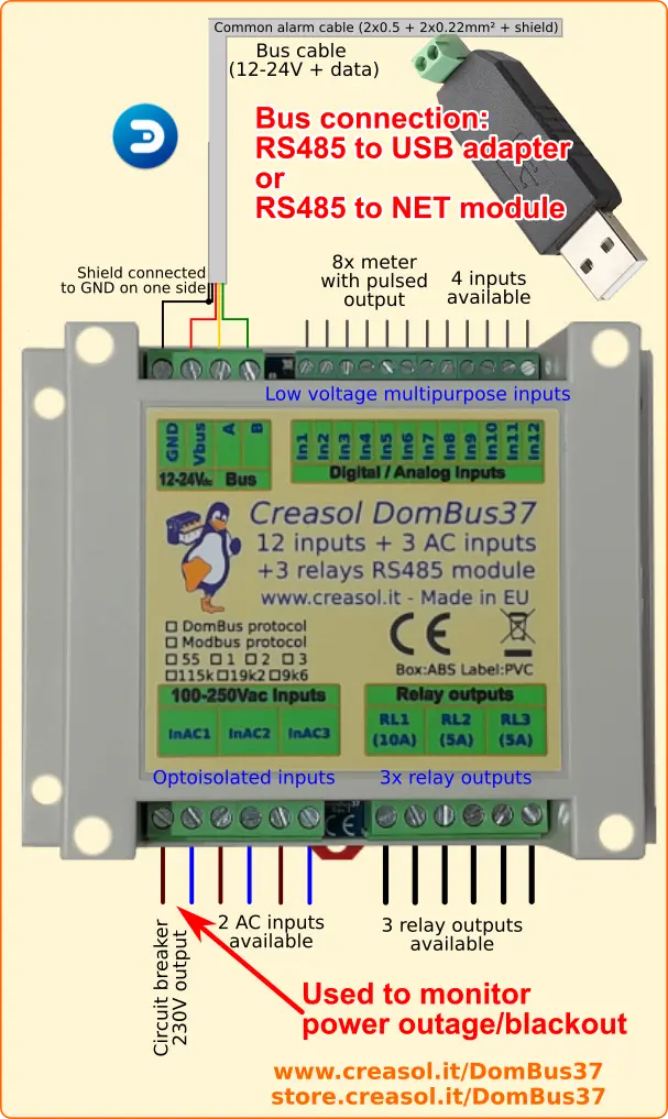
DIN-rail domotic module, 115x90x40mm, supporting both DomBus and Modbus RTU protocols, that integrates 12x low voltage analog/digital inputs, 3x relays outputs, 3x 115Vac / 230Vac inputs. Optionally it is able to control and monitor the power supply fed to a burglar alarm external siren.
Suitable to interface alarm sensors (magnetic contact sensors, PIRs, tampers), monitor power outage (by the 3 AC inputs) and control up to 3 outputs (relays).
It can be connected to the home automation controller by a RS485 serial bus (4 wires, 2 for 12/24V power supply, and 2 for data at 115200bps).
As other DomBus devices, DomBus37 is designed to consume low power, be reliable, fully configurable and easy to use. Each input port is fully configurable, for example as analog or digital input, twinbutton (double button connected to a single port), counter, buzzer, NTC 10k, ... Analog ports are able to decode single, double, triple, quadruple balanced alarm sensors.
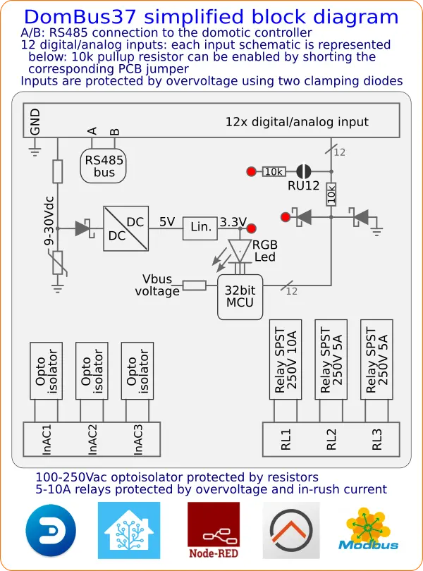
Features ![Block diagram for DomBus37 domotic module with 12 inputs, 3 AC inputs and 3 relay outputs]()
![15 inputs + 3 output home automation system module, Modbus RTU or DomBus protocol]()

- 1x 250V 10A relay with N.O. (SPST) connection, configurable in normal or low power mode, blind mode (UP/DOWN motor) and in flash mode (connected to a blinker lamp or siren)
- 2x 250V 5A relays with N.O. (SPST) connection, configurable in normal or low power mode, blind mode (UP/DOWN motor) and in flash mode (connected to a blinker lamp or siren)
- 12x configurable I/Os, each one can be set as digital input (with internal pullhigh, active low), digital input with pulldown (active high: can accept from +3 to +40V voltage), analog input, twinbutton input (double up/down pushbutton connected to a single module input), double-biased or triple-biased alarm sensor (with status 0=Closed, 1=Open, 2=Masked, 3=Tamper, 4=Shortcircuit) using any combination of resistors (some thresholds must be configured to determine each state), counter/meter (energy meter, gas or water meter); an internal 10k pullup that can be activated by PCB jumper (needed for twinbutton and NTC10k sensors)
- 3x 115Vac / 230Vac optoisolated inputs, that can be used as digital input (to detect voltage on appliances, PIRs, and detect power outage) or counter (meter with AC output)
- Optionally, activated by some PCB jumpers, it can supply an alarm siren monitoring the siren voltage, current and status / errors.
- Monitor bus voltage
- The 12 input ports are protected by clamping diodes and can operate between -40V and +40V.
- 9-35Vdc power supply (internally regulated by a high efficiency switching mode power supply circuitry that minimize power consumption and dissipation)
- low power consumption: 12mW normally, 180mW with the 3 relays ON
- 115200 bps RS485 bus (max length: 1km)
- DomBus proprietary protocol, working with Domoticz home automation system, or Modbus RTU standard protocol, working with Node-RED, Home Assistant, OpenHAB, and many other systems.
Warnings
- Do not mix high and low voltage devices on relay outputs: relays may be used all connected to 115 / 230Vac devices, or all connected to 30Vmax devices.
- Use a 4 wires shielded cable for the bus, using two lines to feed power supply (12 or 24Vdc) protected by a fuse.
- To reduce noise and reflections on the bus, enable the termination resistor (shorting Rbus PCB jumper behind the LED) on the two furthest ends of the bus.

DomBus37 Ports capabilities
Default address: 0xff37
| Port# | Name | Capabilities | Default configuration | Description |
| 1 | IN1 | IN_DIGITAL, IN_DIGITAL_PULLDOWN, IN_ANALOG, IN_TWINBUTTON, SENSOR_ALARM, IN_COUNTER | IN_DIGITAL |
Input, with optional 10k pullup (pcb jumper) and internal pulldown (activated when configured as IN_DIGITAL_PULLDOWN). If connected to a single pushbutton switch or an alarm sensor, the common is GND (when switch is ON, it have to short the port to GND). Can be connected to external NTC thermistor (air or water temperature sensor). |
| 2 | IN2 | IN_DIGITAL, IN_DIGITAL_PULLDOWN, IN_ANALOG, IN_TWINBUTTON, SENSOR_ALARM, IN_COUNTER | IN_DIGITAL |
Input, with optional 10k pullup (pcb jumper) and internal pulldown (activated when configured as IN_DIGITAL_PULLDOWN). If connected to a single pushbutton switch or an alarm sensor, the common is GND (when switch is ON, it have to short the port to GND). Can be connected to external NTC thermistor (air or water temperature sensor). |
| 3 | IN3 | IN_DIGITAL, IN_DIGITAL_PULLDOWN, IN_ANALOG, IN_TWINBUTTON, SENSOR_ALARM, IN_COUNTER | IN_DIGITAL |
Input, with optional 10k pullup (pcb jumper) and internal pulldown (activated when configured as IN_DIGITAL_PULLDOWN). If connected to a single pushbutton switch or an alarm sensor, the common is GND (when switch is ON, it have to short the port to GND). Can be connected to external NTC thermistor (air or water temperature sensor). |
| 4 | IN4 | IN_DIGITAL, IN_DIGITAL_PULLDOWN, IN_ANALOG, IN_TWINBUTTON, SENSOR_ALARM, IN_COUNTER | IN_DIGITAL |
Input, with optional 10k pullup (pcb jumper) and internal pulldown (activated when configured as IN_DIGITAL_PULLDOWN). If connected to a single pushbutton switch or an alarm sensor, the common is GND (when switch is ON, it have to short the port to GND). Can be connected to external NTC thermistor (air or water temperature sensor). |
| 5 | IN5 | IN_DIGITAL, IN_DIGITAL_PULLDOWN, IN_ANALOG, IN_TWINBUTTON, SENSOR_ALARM, IN_COUNTER | IN_DIGITAL |
Input, with optional 10k pullup (pcb jumper) and internal pulldown (activated when configured as IN_DIGITAL_PULLDOWN). If connected to a single pushbutton switch or an alarm sensor, the common is GND (when switch is ON, it have to short the port to GND). Can be connected to external NTC thermistor (air or water temperature sensor). |
| 6 | IN6 | IN_DIGITAL, IN_DIGITAL_PULLDOWN, IN_ANALOG, IN_TWINBUTTON, SENSOR_ALARM, IN_COUNTER | IN_DIGITAL |
Input, with optional 10k pullup (pcb jumper) and internal pulldown (activated when configured as IN_DIGITAL_PULLDOWN). If connected to a single pushbutton switch or an alarm sensor, the common is GND (when switch is ON, it have to short the port to GND). Can be connected to external NTC thermistor (air or water temperature sensor). |
| 7 | IN7 | IN_DIGITAL, IN_DIGITAL_PULLDOWN, IN_ANALOG, IN_TWINBUTTON, SENSOR_ALARM, IN_COUNTER | IN_DIGITAL |
Input, with optional 10k pullup (pcb jumper) and internal pulldown (activated when configured as IN_DIGITAL_PULLDOWN). If connected to a single pushbutton switch or an alarm sensor, the common is GND (when switch is ON, it have to short the port to GND). Can be connected to external NTC thermistor (air or water temperature sensor). |
| 8 | IN8 | IN_DIGITAL, IN_DIGITAL_PULLDOWN, IN_ANALOG, IN_TWINBUTTON, SENSOR_ALARM, IN_COUNTER | IN_DIGITAL |
Input, with optional 10k pullup (pcb jumper) and internal pulldown (activated when configured as IN_DIGITAL_PULLDOWN). If connected to a single pushbutton switch or an alarm sensor, the common is GND (when switch is ON, it have to short the port to GND). Can be connected to external NTC thermistor (air or water temperature sensor). |
| 9 | IN9 | IN_DIGITAL, IN_DIGITAL_PULLDOWN, IN_ANALOG, IN_TWINBUTTON, SENSOR_ALARM, IN_COUNTER | IN_DIGITAL |
Input, with optional 10k pullup (pcb jumper) and internal pulldown (activated when configured as IN_DIGITAL_PULLDOWN). If connected to a single pushbutton switch or an alarm sensor, the common is GND (when switch is ON, it have to short the port to GND). Can be connected to external NTC thermistor (air or water temperature sensor). |
| 10 | IN10 | IN_DIGITAL, IN_DIGITAL_PULLDOWN, IN_ANALOG, IN_TWINBUTTON, SENSOR_ALARM, IN_COUNTER | IN_DIGITAL |
Input, with optional 10k pullup (pcb jumper) and internal pulldown (activated when configured as IN_DIGITAL_PULLDOWN). If connected to a single pushbutton switch or an alarm sensor, the common is GND (when switch is ON, it have to short the port to GND). Can be connected to external NTC thermistor (air or water temperature sensor). |
| 11 | IN11 | IN_DIGITAL, IN_DIGITAL_PULLDOWN, IN_ANALOG, IN_TWINBUTTON, SENSOR_ALARM, IN_COUNTER | IN_DIGITAL |
Input, with optional 10k pullup (pcb jumper) and internal pulldown (activated when configured as IN_DIGITAL_PULLDOWN). If connected to a single pushbutton switch or an alarm sensor, the common is GND (when switch is ON, it have to short the port to GND). Can be connected to external NTC thermistor (air or water temperature sensor). |
| 12 | IN12 | IN_DIGITAL, IN_DIGITAL_PULLDOWN, IN_ANALOG, IN_TWINBUTTON, SENSOR_ALARM, IN_COUNTER, CUSTOM | IN_DIGITAL |
Input, with optional 10k pullup (pcb jumper) and internal pulldown (activated when configured as IN_DIGITAL_PULLDOWN). If connected to a single pushbutton switch or an alarm sensor, the common is GND (when switch is ON, it have to short the port to GND). Can be connected to external NTC thermistor (air or water temperature sensor). |
| 13 | INAC1 | IN_AC, IN_COUNTER | IN_AC | Optoisolated input, that can be connected to a circuit breaker (to notify power outages, expecially for fridges and heat pumps), PIRs with 230V output (to monitor presence), light and appliances (to monitor when light or devices are ON). |
| 14 | INAC2 | IN_AC, IN_COUNTER | IN_AC | Optoisolated input, that can be connected to a circuit breaker (to notify power outages, expecially for fridges and heat pumps), PIRs with 230V output (to monitor presence), light and appliances (to monitor when light or devices are ON). |
| 15 | INAC3 | IN_AC, IN_COUNTER | IN_AC | Optoisolated input, that can be connected to a circuit breaker (to notify power outages, expecially for fridges and heat pumps), PIRs with 230V output (to monitor presence), light and appliances (to monitor when light or devices are ON). |
| 16 | RL1 | OUT_DIGITAL, OUT_RELAY_LP, OUT_BLIND,OUT_FLASH | OUT_RELAY_LP | SPST relay output, NO contact, 10A 250Vac or 30Vdc output capability. Relay contact is protected by varistor. |
| 17 | RL2 | OUT_DIGITAL, OUT_RELAY_LP, OUT_BLIND,OUT_FLASH | OUT_RELAY_LP | SPST relay output, NO contact, 5A 250Vac or 30Vdc output capability. Relay contact is protected by varistor. |
| 18 | RL3 | OUT_DIGITAL, OUT_RELAY_LP, OUT_BLIND(1),OUT_FLASH | OUT_RELAY_LP | SPST relay output, NO contact, 5A 250Vac or 30Vdc output capability. Relay contact is protected by varistor. |
| 19 | VBus | CUSTOM | CUSTOM | 12-24V bus voltage, in mW (for example 13508 for 13.508mV) |
| 20 | S.Volt | CUSTOM | CUSTOM | Voltage on the Siren port (IN12 terminal block) in mV. For more information, check paragraph below. |
| 21 | S.Curr | CUSTOM | CUSTOM | Current on the Siren port (IN12 terminal block) in mA. For more information, check paragraph below. |
| 22 | S.On | CUSTOM | CUSTOM | On/Off entity, to enable/disable power supply to the siren. For more information, check paragraph below. |
| 23 | S.State | CUSTOM | CUSTOM | Siren power status. For more information, check paragraph below. |
(1): can be used as BLIND output, to open a blind/curtain, but only the previous port can be configured in Domoticz as OUT_BLIND because, when configured as OUT_BLIND, DomBus device automatically configure the next port to drive a relay in open direction.
DomBus37 Modbus RTU capabilities (for the Modbus version)
At power-on, the module shows on red LED the current Modbus slave address (register address=8192) in decimal format, on green LED the serial baudrate (reg. 8193), and finally on red LED the serial parity (reg. 8194).
If a value is zero, a long flash is emitted.
For example, if reg(8192)=55, reg(8193)=0, reg(8194)=0, at power the following led flashes will be shown:
5 red flashes, pause, 5 red flashes (slave address= 0x37 = 55 decimal), pause, 1 long green flash (reg(8193)=0 => baudrate=115200bps), pause, 1 long red flash (reg(8194)=0 => parity=None).
Device will be operative only when address/baudrate/parity parameters have been shown: then module will accept commands by Modbus RTU, and periodically shows output status for all ports, from 1 to max port: green flash means that port status is Off, red flash means that port is On.
Default slave address: 55 (0x37)
| Addr | Name | Values | Description |
| 0 | IN1 | 0=OFF, 1=ON, or 0-65535 if port is configured as analog, or 0-4 if configured as SENSOR_ALARM. See below for more information. |
Digital input or analog input, with internal pullup enabled by hardware, or internal pulldown enabled by software (configuring as IN_DIGITAL_PULLDOWN). |
| 1 | IN2 | 0=OFF, 1=ON, or 0-65535 if port is configured as analog, or 0-4 if configured as SENSOR_ALARM. See below for more information. |
Digital input or analog input, with internal pullup enabled by hardware, or internal pulldown enabled by software (configuring as IN_DIGITAL_PULLDOWN). |
| 2 | IN3 | 0=OFF, 1=ON, or 0-65535 if port is configured as analog, or 0-4 if configured as SENSOR_ALARM. See below for more information. |
Digital input or analog input, with internal pullup enabled by hardware, or internal pulldown enabled by software (configuring as IN_DIGITAL_PULLDOWN). |
| 3 | IN4 | 0=OFF, 1=ON, or 0-65535 if port is configured as analog, or 0-4 if configured as SENSOR_ALARM. See below for more information. |
Digital input or analog input, with internal pullup enabled by hardware, or internal pulldown enabled by software (configuring as IN_DIGITAL_PULLDOWN). |
| 4 | IN5 | 0=OFF, 1=ON, or 0-65535 if port is configured as analog, or 0-4 if configured as SENSOR_ALARM. See below for more information. |
Digital input or analog input, with internal pullup enabled by hardware, or internal pulldown enabled by software (configuring as IN_DIGITAL_PULLDOWN). |
| 5 | IN6 | 0=OFF, 1=ON, or 0-65535 if port is configured as analog, or 0-4 if configured as SENSOR_ALARM. See below for more information. |
Digital input or analog input, with internal pullup enabled by hardware, or internal pulldown enabled by software (configuring as IN_DIGITAL_PULLDOWN). |
| 6 | IN7 | 0=OFF, 1=ON, or 0-65535 if port is configured as analog, or 0-4 if configured as SENSOR_ALARM. See below for more information. |
Digital input or analog input, with internal pullup enabled by hardware, or internal pulldown enabled by software (configuring as IN_DIGITAL_PULLDOWN). |
| 7 | IN8 | 0=OFF, 1=ON, or 0-65535 if port is configured as analog, or 0-4 if configured as SENSOR_ALARM. See below for more information. |
Digital input or analog input, with internal pullup enabled by hardware, or internal pulldown enabled by software (configuring as IN_DIGITAL_PULLDOWN). |
| 8 | IN9 | 0=OFF, 1=ON, or 0-65535 if port is configured as analog, or 0-4 if configured as SENSOR_ALARM. See below for more information. |
Digital input or analog input, with internal pullup enabled by hardware, or internal pulldown enabled by software (configuring as IN_DIGITAL_PULLDOWN). |
| 9 | IN10 | 0=OFF, 1=ON, or 0-65535 if port is configured as analog, or 0-4 if configured as SENSOR_ALARM. See below for more information. |
Digital input or analog input, with internal pullup enabled by hardware, or internal pulldown enabled by software (configuring as IN_DIGITAL_PULLDOWN). |
| 10 | IN11 | 0=OFF, 1=ON, or 0-65535 if port is configured as analog, or 0-4 if configured as SENSOR_ALARM. See below for more information. |
Digital input or analog input, with internal pullup enabled by hardware, or internal pulldown enabled by software (configuring as IN_DIGITAL_PULLDOWN). |
| 11 | IN12 | 0=OFF, 1=ON, or 0-65535 if port is configured as analog, or 0-4 if configured as SENSOR_ALARM. See below for more information. |
Digital input or analog input, with internal pullup enabled by hardware, or internal pulldown enabled by software (configuring as IN_DIGITAL_PULLDOWN). Configure as CUSTOM port to enable Siren management (power supply + monitoring) |
| 12 | INAC1 | 0=OFF (floating), 1=ON (100-250V signal detected) | Optoisolated input that can be connected to circuit breaker output, appliances, lights, PIRs, to monitor the voltage applied to those devices determining the status (ON/OFF) and blackout (power outage to fridges, freezers, heat pump, ...) |
| 13 | INAC2 | 0=OFF (floating), 1=ON (100-250V signal detected) | Optoisolated input that can be connected to circuit breaker output, appliances, lights, PIRs, to monitor the voltage applied to those devices determining the status (ON/OFF) and blackout (power outage to fridges, freezers, heat pump, ...) |
| 14 | INAC3 | 0=OFF (floating), 1=ON (100-250V signal detected) | Optoisolated input that can be connected to circuit breaker output, appliances, lights, PIRs, to monitor the voltage applied to those devices determining the status (ON/OFF) and blackout (power outage to fridges, freezers, heat pump, ...) |
| 15 | RL1 | 0=OFF, 1 or 65280=ON, 2-65279=ON for specified time. Logic can be inverted specifying the INVERTED option (on address 512+port) |
SPST relay output, NO contact, 10A 250Vac or 30Vdc output capability. Relay contact is protected by varistor |
| 16 | RL2 |
0=OFF, 1 or 65280=ON, 2-65279=ON for specified time.Logic can be inverted specifying the INVERTED option (on address 512+port) |
SPST relay output, NO contact, 5A 250Vac or 30Vdc output capability. Relay contact is protected by varistor |
| 17 | RL3 | 0=OFF, 1 or 65280=ON, 2-65279=ON for specified time. Logic can be inverted specifying the INVERTED option (on address 512+port) |
SPST relay output, NO contact, 5A 250Vac or 30Vdc output capability. Relay contact is protected by varistor |
| 18 | Bus voltage | Voltage on bus, in mV (e.g. 13502=13.502V) | Vbus voltage |
| 19 | Siren Voltage | Voltage on the siren port (IN12) in mV (e.g. 12800=12.8V) | Check the section below for more information about feeding and monitoring an external siren |
| 255 | All input ports | bitmask: 1=> IN1, 2=>IN2, 4=>IN3 ... 0x1000=>INAC1, 0x2000=>INAC2, 0x4000=>INAC3 |
This address is used to check input state in one command |
| 256-273 | Port config | 1=OUT_DIGITAL, 2=OUT_RELAY_LP, ... |
Command used to configure port 1 (256), port 2 (257), ... as OUT_DIGITAL or OUT_RELAY_LP (low power consumption relay) or other value (see table below) |
| 512-529 | Port option | 0=NORMAL, 1=INVERTED (output normally ON, or input is ON when port voltage is 0V) | Set port option. If set to 1, output stays ON after boot until the port is asserted (then relays goes OFF). For inputs, setting INVERTED the port value is ON (1) when input voltage is 0V, OFF when input is left open with internal pullhigh enabled. |
| 8192 | Slave Address | 1-247 | Permits to change the slave address of the module, so it's possible to add other modules to the same bus |
| 8193 | Serial bitrate | 0=115200bps, 1=57600, 2=38400, 3=19200, 4=9600, 5=4800, 6=2400, 7=1200bps | Serial speed, default 115200 bps 8,n,1 |
| 8194 | Serial parity | 0=None, 1=Even, 2=Odd | Serial parity, default none (115200 bps 8,n,1) |
| 8198 | Revision, major | Read only | Get firmware version, major number. For example "02" means that revision is "02XX" where XX defined by parameter 8199 |
| 8199 | Revision, minor | Read only | Get firmware version, minor number. For example "h1" means that revision is "XXh1" where XX defined by parameter 8198 |
| 9000 | Invert logic on all 12 inputs | 0: normal logic state (reset INVERTED option on all inputs IN1-IN12) 1: inverted logic (set INVERTED option on all inputs IN1-IN12) |
This parameter can be used to invert the logic level associated to all IN1-IN12 inputs without the need to write the INVERTED options to register 512,513,...,523 |
It's possible to activate one or more outputs for a certain amount of time (monostable/timer output) as indicated in the table. The parameter corresponding to the needed time can be computed using the following rules:
From 0 to 60s => 31.25ms resolution 2=62.5ms, 3=93.75ms, ... 1920=60s => value=time_in_milliseconds/31.5
From 1m to 1h with 1s resolution 1921=61s, 3540+1920=5460=1h => value=(time_in_seconds-60)+1920
From 1h to 1d with 1m resolution 5461=1h+1m, 1380+5460=6840=24h => value=(time_in_minutes-60)+5460
From 1d to 1500 days with 1h resolution 6841=25h, 6842=26h, and so on => value=(time_in_hours-24)+6840
The following tables show some Modbus commands examples.
| Slave Addr | Func. Code | Reg.Addr | Reg.Value | Frame | Description |
| 55 | 06 | 8192 | 1 | [37][06][20][00][00][01][xx][xx] | Change slave address from 54 (0x36) to 1 |
| 01 | 06 | 8193 | 4 | [01][06][20][01][00][04][D2][09] | Set serial speed to 9600bps |
| 01 | 06 | 8194 | 1 | [01][06][20][02][00][01][E2][0A] | Set even parity |
| 49 | 10 | 8192 | 1,4,1 | [31][10][20][00][00][03][06][00][01][00][04][00][01][B1][71] | With a single command, set slave address to 1, serial speed to 9600bps, even parity. Original modules address was 49 (0x31) in this example. |
| 01 | 06 | 0 | 65280 | [01][06][00][00][FF][00][C8][3A] | Activate RL1 output forever (65280=0xff00) |
| 01 | 06 | 1 | 960 | [01][06][00][01][03][C0][D8][AA] | Activate RL2 for 960/32=30s |
| 01 | 06 | 255 | 0 | [01][06][00][FF][00][00][B9][FA] | Disable all outputs (Reg.Addr=255) |
| 01 | 10 | 0 | 32,0,0,65280 | [31][10][00][00][00][04][08][00][20][00][00][00][00][FF][00][E6][5C] | Set RL1 On for 1s (32), RL2 Off, RL3 Off, RL4 On - Max 10 registers can be set in one command |
| 01 | 03 | 255 | 1 | [01][03][00][FF][00][01][B4][3A] | Read a 16bit value with ports status. For example if returned value is 0xd1 (0b11010001), output status is: RL8=On, RL7=On, RL6=Off, RL5=On, RL4=Off, RL3=Off, RL2=Off, RL1=On |
| 01 | 03 | 8198 | 2 | [01][03][20][06][00][02][2F][CA] | Read 4 bytes within module version. For example, if returned value is <30><32><68><31> (in hex format), the corresponding ASCII value is "02h1" (Firmware 02h1) |
| 01 | 0F | 0 | 8,1,0xd1 | [01][0F][00][00][00][08][01][D1][3E][C9] | Set coil status to 0xd1 (0b11010001), activating RL8, RL7, RL5, RL1 and disabling other relays |
| 01 | 01 | 0 | 8 | [01][01][00][00][00][08][3D][CC] | Read coil status. If returned value is 0xd1 (0b11010001), it means that RL8, RL7, RL5 and RL1 are On |
Modbus protocol can be tested easily using a modbus program, like mbpoll for Linux:
mbpoll -v -m rtu -0 -1 -a1 -b115200 -Pnone -r 0 /dev/ttyUSB0 32 0 64 128 0 0 0 65280
to activate RL1 for 1s, R3 for 2s, RL4 for 4s and RL8 forever.
mbpoll -v -m rtu -0 -1 -a1 -b115200 -Pnone -r 255 -c 1 /dev/ttyUSB0
to read all port states.
Using input ports to read external DC voltages
Voltages applied to a DomBus module input must be in the range 0-3.3Vdc, so an external resistive partition should be applied to measure higher voltage.
For example, to monitor a 12V voltage, a resistive partition with 100k and 22k can be used: in this case max applied voltage = 3.3 / 22k * (100k + 22k) = 18.3V and the A constant used in the domotic controller to get the real voltage is calculated as 18.3/65535=0.00027924
Please note that analog voltage can be applied only to module ports without the 10k pullup resistor.
Take care to measure voltages only on devices that share the same ground (GND) of the DomBus network!
Using input ports to read temperatures
DomBus modules have the ability to read temperature by using NTC sensors with 10k resistance @25°C and B=3950 coefficient.
NTC should be connected to inputs that already have the internal 10k pullup resistor, otherwise an external 10k resistor must be applied. Connect NTC sensor between input and GND.
Setting IN_ANALOG,FUNCTION=3950 the module port is configured in analog mode, and DomBus driver will convert the read value to the temperature value in °C.
When using Modbus protocol, the analog value returned by the module should be converted, by software, using the following formula:
Ro=10000To=25.0beta=3950#value=0..65535, value returned by DomBus moduleif (value==65535): value=65534 #Avoid division by zeror=value*Ro/(65535-value)temp=math.log(r / Ro) / betatemp+=1.0/(To + 273.15)temp=round((1.0/temp)-273.15, 2)
Application notes
Connecting up to 12 temperature sensors to DomBus37, to monitor green houses, heating systems, ...
All analog/digital inputs of DomBus37 can be configured as IN_DIGITAL,FUNCTION=3950 and connected to standard NTC thermistors, 10k @25°C with 3950 constant: in this way it's possible to measure up to 12 fluid or air temperatures (room, tunnel or greenhouse temperatures, soil temperatues, heating and boiler water temperatures, ....).
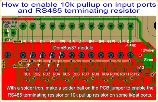
For each input connected to a NTC temperature sensor, the 10k pullup should be enabled (by shorting the relative RUx PCB jumper). For example, if IN1 is connected to NTC, RU1 should be shorted by a using the solder iron and some tin to short the PCB pads marked as RU1.
In case of DomBus protocol, the NTC device should be configured as IN_ANALOG,FUNCTION=3950 , so the DomBus37 module will periodically send out a value between 0 and 65535 corresponding to the partition voltage determined by 10k and NTC, that will be converted by the DomBus library/plugin to a temperature value in Celsius.
Monitoring the power supply of an outdoor burglar alarm siren
This is an experimental feature, not well tested so no warranty is given on this solution.
DomBus37 permits to feed power supply to an outdoor siren, monitoring the current to the siren: since every outdoor siren has a battery inside, it's possible that battery is damaged by internal element short circuit, leading to a lower battery voltage and higher current sinking. In this case it's useful to monitor outdoor sirens to check its battery status.
To prevents any troubles, a current limiter is placed in DomBus37, limiting current to 450mA max, and a mosfet to switch power supply ON and OFF. Normally, when the power supply is switched OFF, the siren starts sounding, so normally the siren is always supplied and power supply is removed in case of intrusion or alarm.
To activate this feature, the IN12 port must be configured as CUSTOM (by default it's configured as digital input), 3 PCB jumper marked as "Siren" should be closed (tin ball with a solder iron) and "In12" PCB jumper should be open (using a cutter).
Connecting the positive power supply of outdoor siren to IN12 terminal block, and enabling S.On port, the device will start measuring:
- Vbus (13.5-13.8V, normally), with 1mV resolution
- S.Volt is the siren voltage (voltage on IN12 terminal block), with 1mV resolution
- S.Curr is the siren current (current to the siren), with 1mA resolution
Also, the S.State port will show the current status of siren, showing if the siren is ON or OFF, sinking an high current, or has a low voltage, or if the siren has been disabled due to a high current and low voltage leading to a high power dissipation on the mosfet inside the module.
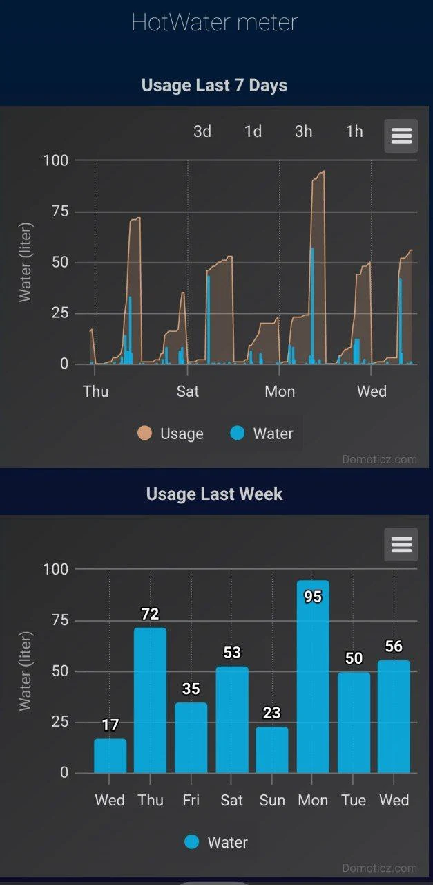
Interfacing a water flow sensor
 Water flow sensors are useful to measure the cold and hot water consumption. Some water flux sensors are based on a hall sensor to measure the internal rotor spin, generating pulses up to 100-200 Hz.
Hall water flow sensors are not sensitive sensors, expecially if iron made like the one shown in the picture, so we suggest to choose meters with the best sensitivity, for example 1-30 l/min, using brass material: be careful that if flow rate is lower than 1 liter per minute, sensor will output 0 pulses!
DomBus modules are able to work with high speed sensors, generating up to 500 pulses/seconds.
The picture below shows how DomBus37 has been connected to some temperature sensors, alarm sensors, water flow sensor and power/energy meters.

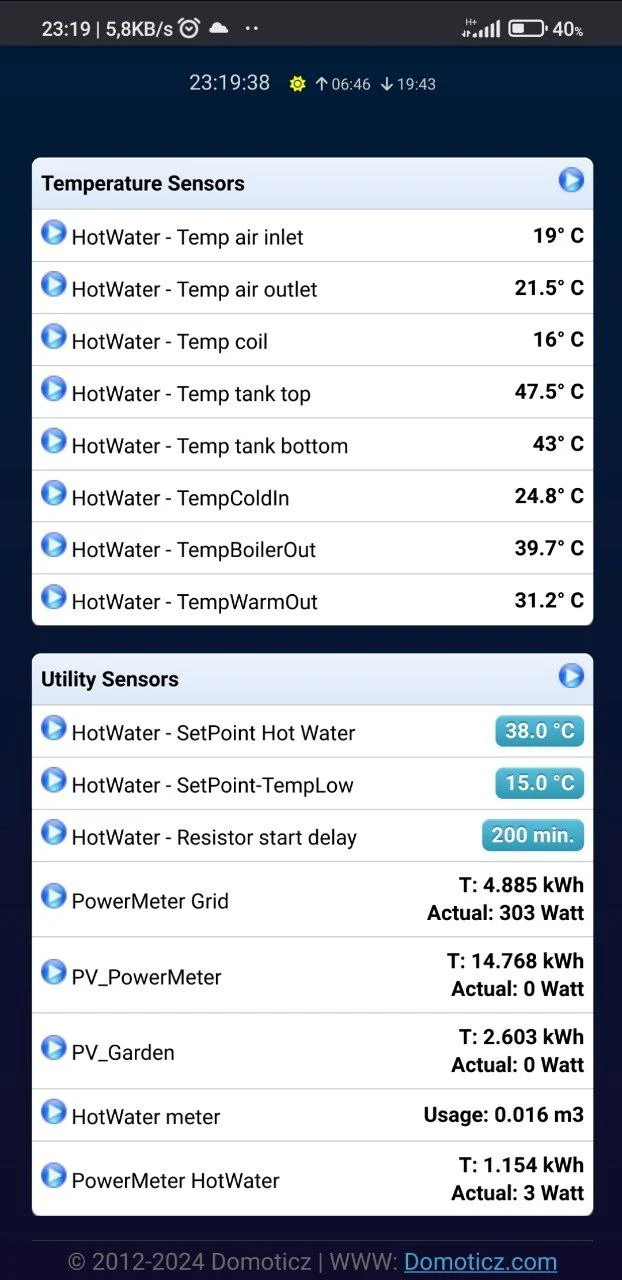
When DomBus modules are used with Domoticz, (in this case, DomBus37 module programmed with DomBus protocol):
- NTC temperature sensors (10k at 25°C, B=3950) are configured as IN_ANALOG,FUNCTION=3950;
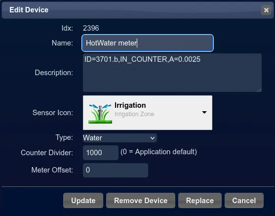
- water flow meter is configured as IN_COUNTER,A=0.0025 (400 pulses per liter) with divider parameter=1000 to convert from litre to m³;
- power/energy meters (DDS238-2) are configured as IN_COUNTER,TYPENAME=kWh,DIVIDER=2000
Using DomBus37 to monitor kWh meters and power outage
DomBus37 has 12 low voltage inputs that can be configured in many ways: for example they can be connected to kWh meters to show the power and consumed energy.
Also, it has 3 AC inputs that can be used to monitor system and get notification in case of power outage / blackout.
Finally, 3 relays can be used to activate lights, loads, fan, ...
Using input ports to interface alarm sensors configured as double-biased or triple-biased sensors
Each input port can be configured with the 10k pullup resistor (enabling a PCB jumper) and then configured as SENSOR_ALARM to read the status of a double or triple biased sensor. Please check the FAQ below, with detailed description of SENSOR_ALARM
Using DomBus37 with Home Assistant
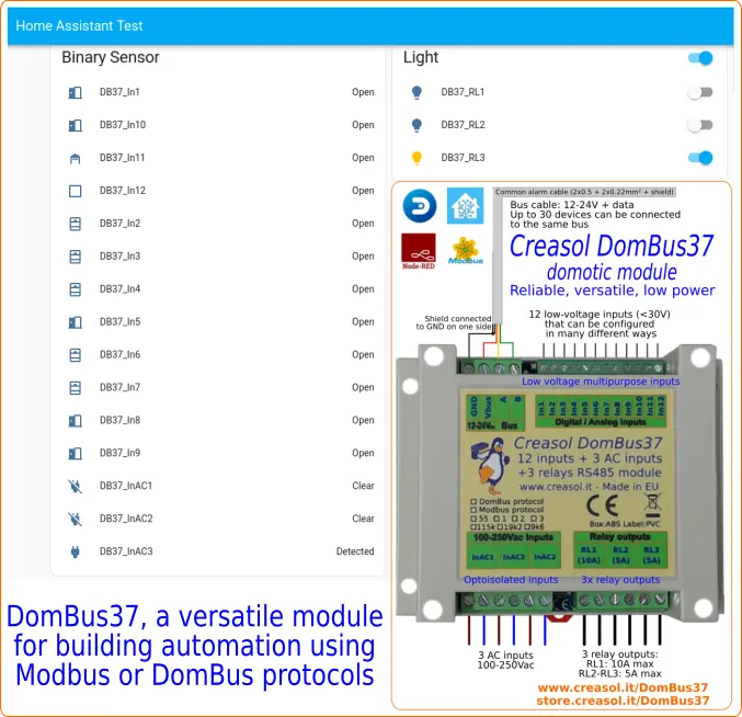 As DomBus modules can be provided with standard Modbus firmware, it's possible to use them with HomeAssistant by using the Modbus integration.
On GitHub it's possible to find configuration examples:
https://github.com/CreasolTech/DomBus_ha
The picture shows the easiest configuration of the module, with 12 inputs and 3 AC inputs ports used as binary sensors, and 3 relay outputs as normal lights.