
Introduction
Why domotize the electric car?
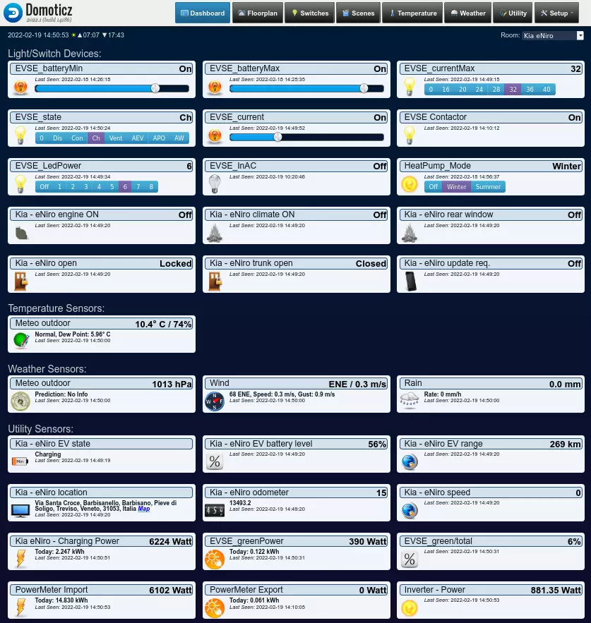
Because in this way you can monitor the electric car parameters from a unique panel where you have all controls of your Smart Home.
Because you can easily monitor the state of charge of the car battery.
Because you can avoid charging when total imported power from the grid is very high, preventing electricity meter disconnections.
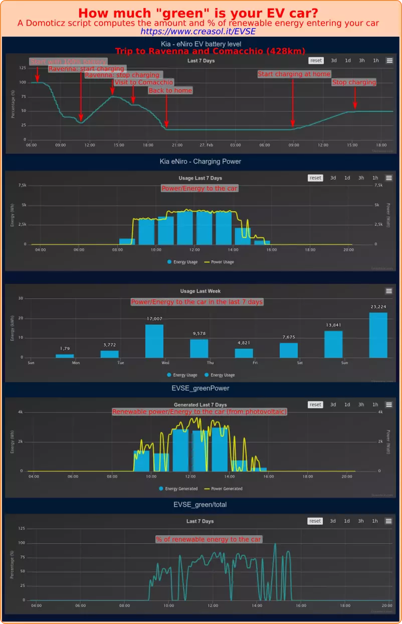
But the most important thing, you can also charge the electric vehicle using the most energy from renewable, for example if you have a solar photovoltaic system.
This article explain two different cheap and smart solutions to charge the electric vehicle battery (electric car, van, scooter, ...):
- Solution 1, using a DomBus EVSE module, that permits to automatically regulate the charging current to improve efficiency and speed
- Solution 2, using the EVSE cable supplied with the car, enabled by Domoticz
Below you will set two different battery level thresholds, in the domotic panel:
- a min battery level below which the car is charged using any kind of electricity source
- a max battery level above which the car stop charging: also, when state of charge is between min and max levels, the car will be charged only when the photovoltaic system produces enough to avoid imporing energy from the grid
Travelling with zero emissions and using only energy from the sun is really awesome!
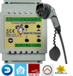
Solution 1: using the Creasol DomBusEVSE module to control the charging current
This is an advanced solution that uses the EVSE (Electric Vehicle Supply Equipment) module Creasol DomBus, that:
- detects plug connection and disconnection
- detects when the electric vehicle starts and stops charging
- detects alarms from vehicle
- interfaces a bidirectional energy meter to know the real time import or export power from grid
- operates as stand-alone (no need for a domotic controller) with the possibility to select two charging mode:
1. use the maximum power allowed by electricity meter, preventing overloads and disconnections
2. use only renewable energy (keep import power around 0W) - operates in a controlled mode, with Domoticz home automation system: in this case it's possible to
1. easily set the minimum and maximum battery level
2. easily set the maximum charging current
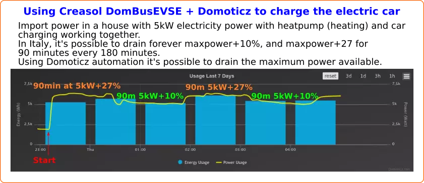
3. when battery level is below minimum, charge at the max power permitted by the electricity meter (in Italy, alternates 90 minutes at maximum power + 27% and 90 minutes at maximum power + 10%, it's not possible to charge faster! The electrical system must be checked carefully when using maximum power, to avoid overheating and fires!!)
4. when battery level is between minimum and maximum, charge using only power from renewable energy from photovoltaic
Prerequisites
- electric vehicle with cloud connection, to know the battery state of charge (not mandatory, but recommended when used inside a home automation system)
- Creasol DomBusEVSE module (under development)
- bidirectional energy meter, to compute the current import power and export power (optional, in case of photovoltaic/wind system)
- circuit breaker with differential protection (residual current block) type-B
- 2P (single phase) or 4P (3-phases) contactor to enable/disable charging
- 32A EV cable with type-2 or type-1 plug on one side
Electric diagram
Which protection should be used?
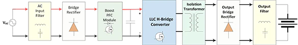
Residual Current Block: the technical norm IEC 61851-1:2017 specify that mode-3 EV charging needs a protection from direct currents above 6mA. Only Type-B RCD provides this feature, while Type-A RCD (a cost-effective solution) does not.
Alternatively, Type-A RCD is sufficient only if an additional equipment to detect DC currents (RDC-DD: Residual Direct Current Detection Device) is used.
The following block diagram (©onsemi - www.onsemi.com) represent the on-board charger placed inside a vehicle: please note the input filter needed to block common-mode (DC) and differential-mode (AC) currents, and the isolation transformer between AC-charger and battery. Is Type-B RCD really needed? The technical norm IEC 61851-1:2017 say yes, anyway, because any DC conducted emissions on mains power can saturate the magnetic circuit inside the Type-A RCD that, in this case, loose the ability to break the circuit in case of shock or leakage.
Domoticz LUA script
In github repository it's possible to find script_device_power.lua, that should be placed in domoticz/scripts/lua directory, that manages EV charging, checks for power imported from the grid disabled or reducing loads when imported power is near the maximum permitted, enable some loads (electric heaters, dehumidifiers, ...) in case of extra production from photovoltaic, shows current power usage/export on red/green LEDs, activate white leds in case of blackout, ...
The building power management can be configured through the config file config_power.lua
Solution 2: using standard EVSE cable
In this case the electric vehicle is connected through the charging cable provided with the vehicle: no need for a wallbox or supplementary EVSE cables.
PROS:
- very cheap solution: don't need for expensive wallbox or EVSE systems. Just use the standard cable provided with the vehicle, and few low-cost devices to enable/disable charge and, possibly, to monitor the energy used to charge the vehicle to make some statistics on energy consumption, EV battery charging efficiency, ...
CONS:
- charging current/power can be manually selected on the EVSE cable, but not automatically, with the result that it's not possible to maximize the own consumption, charging at higher or lower currents depending by the available power from photovoltaic.
Prerequisites
- electric vehicle with cloud connection, to know the battery state of charge
- standard EVSE cable provided with the car / vehicle
- electricity meter, to compute the current power and consumed energy (optional)
- circuit breaker with differential protection (recommended)
- 2P contactor (or relay) to enable/disable charging
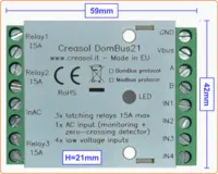
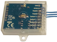
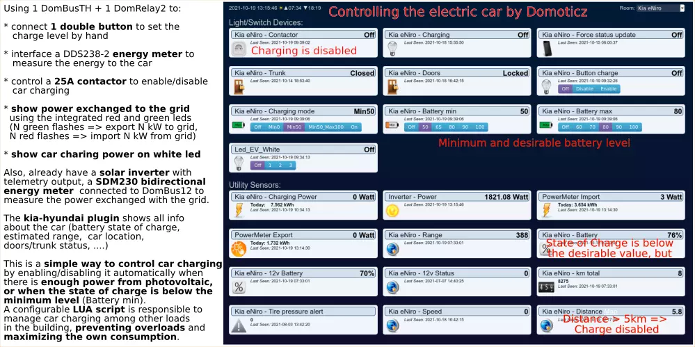
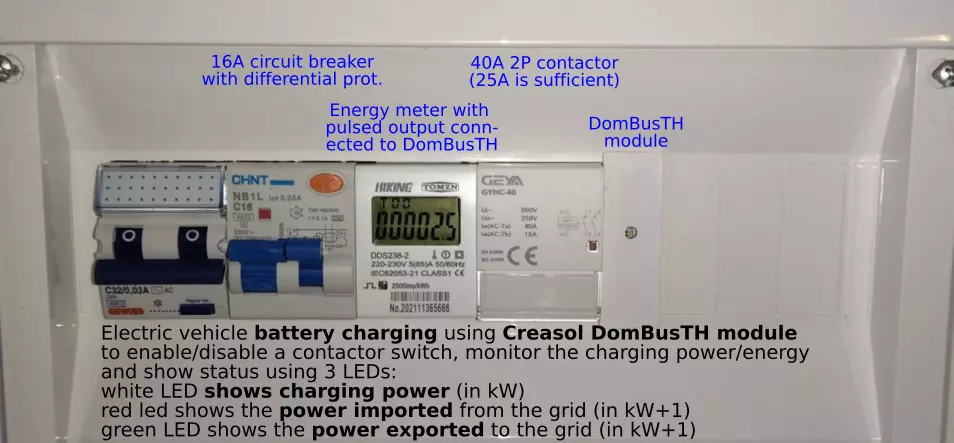
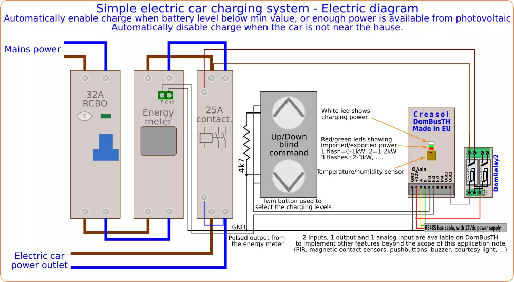
- Creasol DomBus23, to interface electricity meter and contactor to the domotic controller (Home Assistant, Domoticz), or Creasol DomBusTH + DomRelay2 to get 3 LEDs already available to show electric car charging power and total import/export power on the electricity grid.
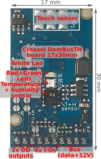
Creasol DomBusTH is a domotic module that can be used with Domoticz and Home Assistant that implements all features needed by this project:
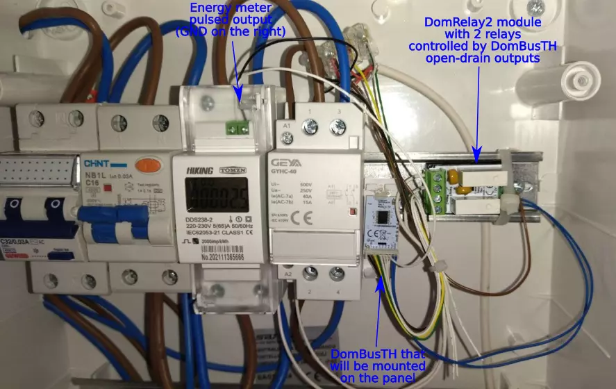
- has 2 open-drain outputs (1 is needed) to enable an external relay (DomRelay2 module) to control the 25A/40A 2P contactor;
- has 4 configurable inputs, 1 of which is configured as IN_COUNTER and connected to the electricity meter to measure the charging power and energy, and 1 input is connected to a dual button to set the charging level easily;
- has 3 LEDs that are used to display the charging status (white led) and current import/export power (red and green leds);
- has temperature and relative humidity sensors that are not important for this application, but can be used to monitor the room temperature.
Also, it has 1 or more analog inputs, buzzer output that are beyond the scope of this project. It's a small electronic board that can be fixed with 2 hot-glue points on a blank cover or modular cover.
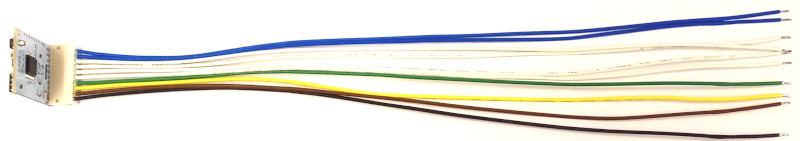
It can be connected to the domotic controller (Raspberry, Nuc, PC, ...) by a common alarm cable (within 4 wires, 2 wires for power supply and 2 for data) using a cheap USB to RS485 adapter. Obviously, dozens of DomBus modules can be connected using the same bus/cable, forming a reliable domotic network optimized for low power consumption that does not use batteries and do not produce RF pollution.
Electric diagram
Domoticz LUA script
In github repository it's possible to find script_device_power.lua, that should be placed in domoticz/scripts/lua directory, that manages EV charging, checks for power imported from the grid disabled or reducing loads when imported power is near the maximum permitted, enable some loads (electric heaters, dehumidifiers, ...) in case of extra production from photovoltaic, shows current power usage/export on red/green LEDs, activate white leds in case of blackout, ...
The building power management can be easily configured through a separate text config file, config_power.lua , so there is no need to put your hands in LUA coding!
Other information about electric vehicles
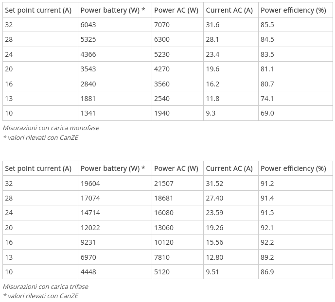
Efficiency charging a Renault Zoe R110 using single-phase and three-phase
Getting high efficiency conversion from AC to DC with single-phase mains supply is very difficult, due to the high ripple on AC/DC conversion: when rectified voltage decreases, the efficiency of the DC/DC boost converter decreases.
For this reason it's important to use 3-phase mains supply to get the higher efficiency while charing the car battery.
The following graphs represents the charging efficiency measured for a Zoe R110 using both single-phase and 3-phase, with different charging power: more info at https://www.azoenzo.com/tempi-di-ricarica-ed-efficienza/
Something about solar photovoltaic systems
To charge the eVehicle, and most important to supply the heat pump in the winter, you should have solar photovoltaic system, but where? On the roof or on the garden? What inclination and orientation for the panels?
In the summer there are no problem at all... the day is long and we always have an over-production. But in the autumn and winter?
The following tables and graphs show a simulation of a 2.7kWp photovoltaic system in 5 configurations and 2 dates (Autumn and Winter), for the Northern Italy, using data from the very useful European website https://ec.europa.eu/jrc/en/pvgis
Simulation using data from 20 September 2016
The following table shows the simulation for the begin of Autumn:
The first column shows the time of the day (GMT+1, not DayLight Saving time!), then second column a simulation for the panels on the roof, oriented to EAST with inclination of only 15 degrees from the horizontal line.
The third column shows the simulation for panels oriented to south direction, 15 degrees inclination.
The forth column shows the simulation for panels in vertical, south direction.
The fifth column shows the simulation of panels in south direction and 70 degrees inclination.
Finally, the sixth column show the performance of a simple solar tracker with vertical axis that can rotate from east toward south and west, with panel inclination 70 degrees.
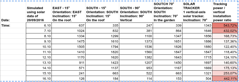
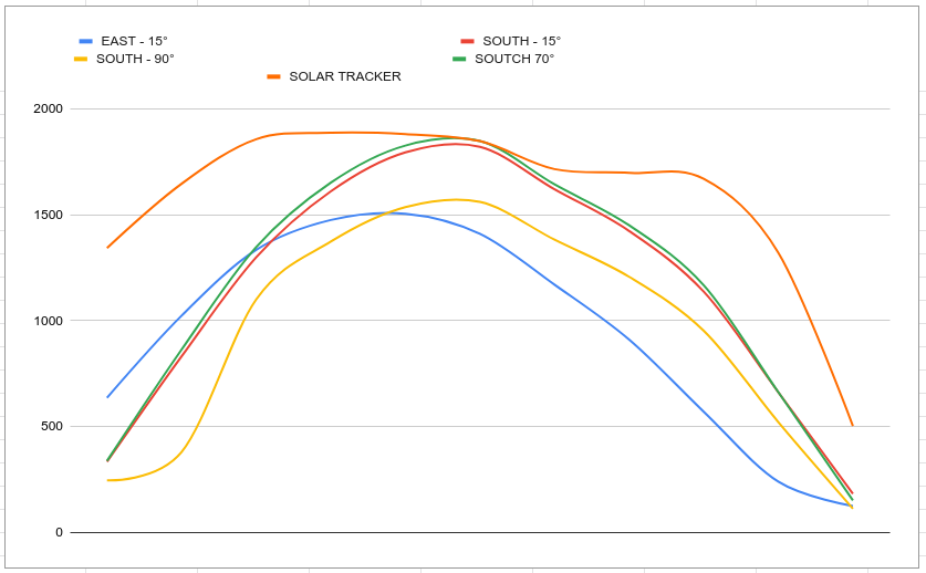
It's possible to see that best performances can be achived using a solar tracker... since from Sunrise, the tracking system lead to a very high power that permits to start heat pump without using power from the grid.
Simulation using data from 1 January 2016
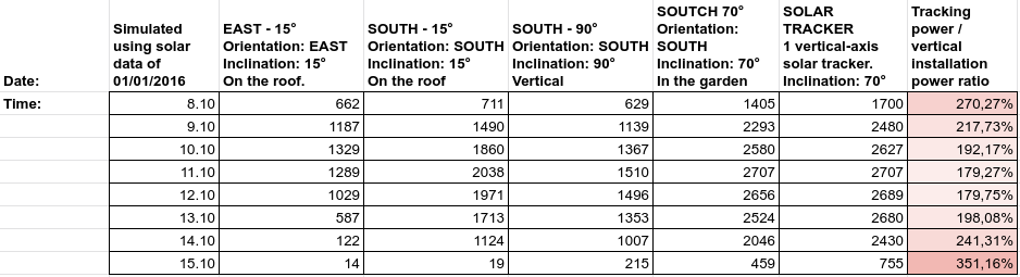
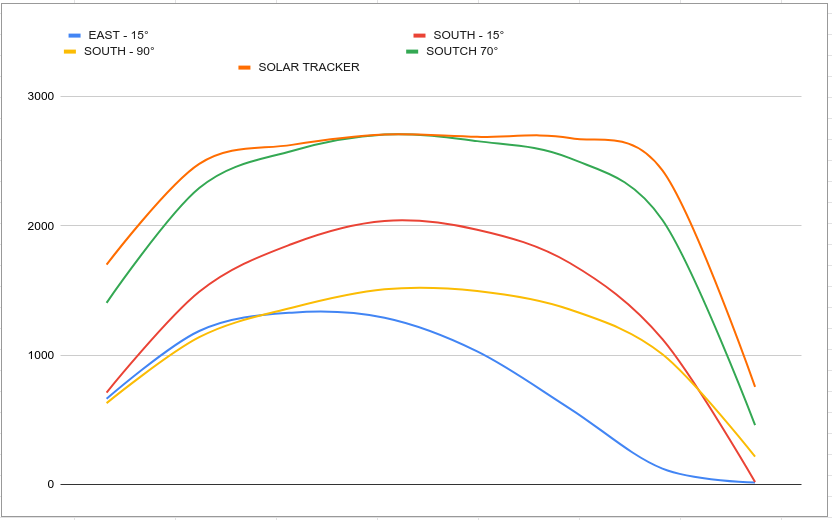
In this case, the solar tracking system does not help to improve the power, because the Sun in the Winter rise from south-east and fall to south-west.