Introduction
DomBus are modules designed for industrial and home automation systems that are available with 2 different protocols:
- DomBus protocol, that is supported by Domoticz home automation controller, is a reliable protocol that permits to manage dozens of modules and get status from modules as soon as they changes. Also it includes the so-called DCMD commands that, similarly to KNX, are transmitted between DomBus modules in the same bus to activate outputs in case of events (switch or pushbutton pressed, temperature value, power value, ....) without needing for the intervention or the home automation controller, useful solution to get a home automation system that works even in case of domotic controller fault. The Creasol DomBus plugin have to be installed in Domoticz, using the Python Plugin Manager or downloading the software from GitHub (see the section below).
- Modbus RTU protocol, widely used in industrial and home automation systems, is supported by almost any domotic controller like Home Assistant, OpenHAB, IObroker, Node-RED, ...
Modbus is a master-slave protocol that permits to activate and deactivate a single relay, all relays or a group of relays by a single command. Also, it's possible to specify, for each relay, the ON time from 31.5ms to 1500 days, so the relay automatically switches OFF after the selected time.
The Modbus RTU version can be used by Node-RED system to realize flows including relay outputs, digital and analog inputs, temperature, humidity, energy sensors, electric vehicle charging station, and more.
Node-RED configuration
First, the modbus palette should be enabled: if not already enabled, type the command
npm install node-red-contrib-modbus
then restart Node-RED.
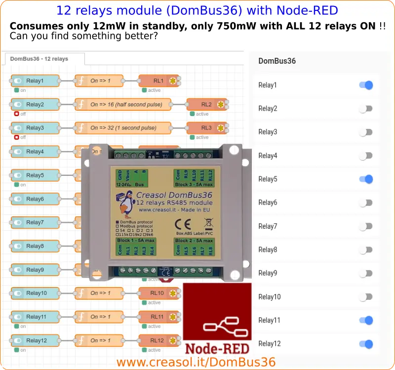
Configuring DomBus31 (8 relays module) or DomBus36 (12 relays module)
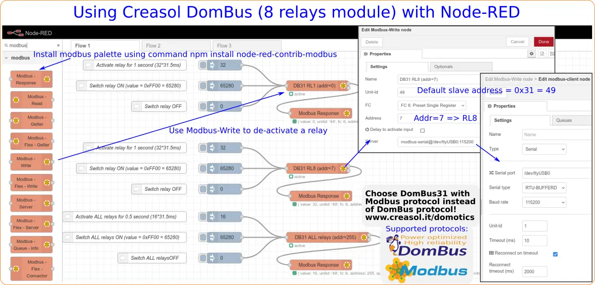
The above flow shows how to use the 8 relays module DomBus31 with Node-RED: drag Modbus-Write to the flow, and configure it as shown in the picture.
To have complete information about DomBus modules, check https://www.creasol.it/domotics
Click to have full information about DomBus31 (8 relays module) and DomBus36 (12 relays module)
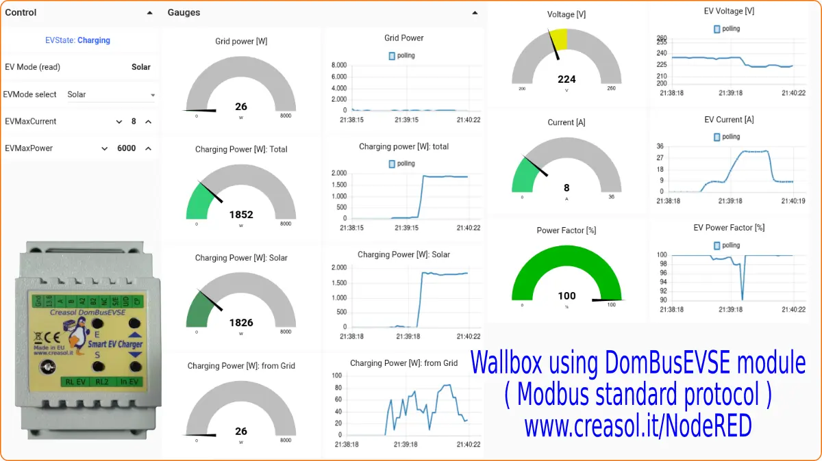
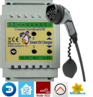
Configuring DomBusEVSE module with NodeRED, to build a smart wallbox EV charging station
DomBusEVSE is a DIN-rail module designed to make a smart EV charging station. It have to be connected to external components like 2P or 4P contactor (single phase or three phase), RCCB protection, optional energy meter for EV energy measure/accounting, optional energy meter for grid power measure/accounting (if already exists, the grid power can be sent to the EVSE module by a simple automation), and EV cable.
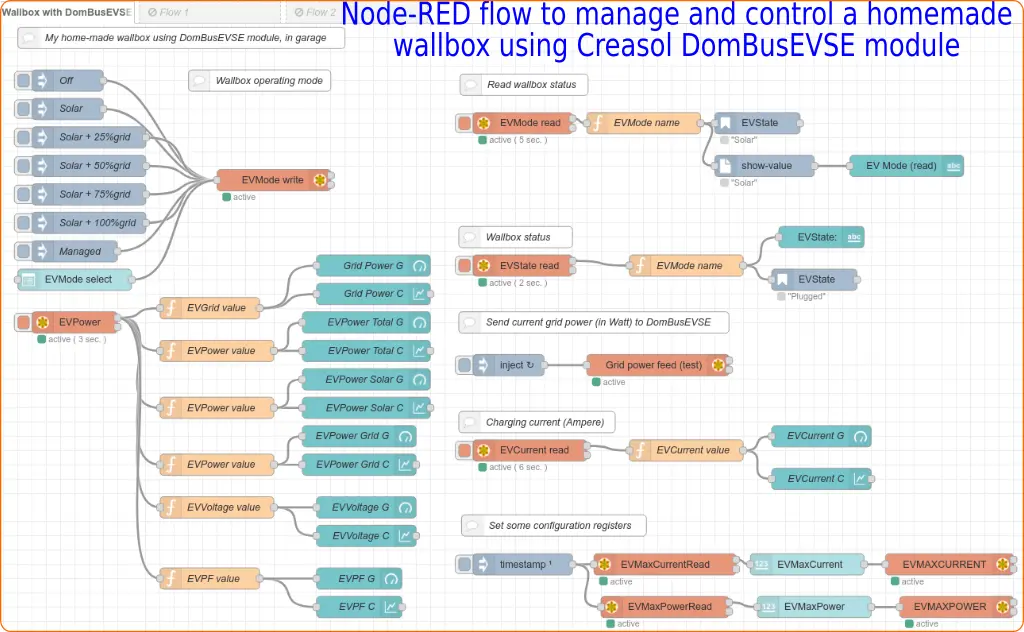
It's possible to set the EVSE module to charge using only renewable power (photovoltaic, wind, ...): in this case the wallbox regulates the charging power to have always negative grid power (no power from the electrical grid). Alternatively, it's possible to set the EVSE to use 25, 50, 75 or 100% of the available power from the grid: in this case setting for example to 50% and having EVMAXPOWER=6000W (max 6000W from grid), the EVSE regulates the charging power to drain no more than 3000W from the grid.