DomBus sind Module für Industrie- und Hausautomationssysteme, die mit zwei verschiedenen Protokollen erhältlich sind:
Das DomBus-Protokoll , das vom Domoticz- Hausautomationscontroller unterstützt wird, ist ein zuverlässiges Protokoll, das die Verwaltung Dutzender Module ermöglicht und den Status von Modulen abruft, sobald sie sich ändern. Es beinhaltet auch die sogenannten DCMD- Befehle, die ähnlich wie bei KNX zwischen DomBus-Modulen im selben Bus übertragen werden, um bei Ereignissen (Schalter- oder Tasterbetätigung, Temperaturwert, Leistungswert, ...) Ausgänge zu aktivieren, ohne dass dies erforderlich ist für den Eingriff oder den Hausautomationsregler, eine nützliche Lösung, um ein Hausautomationssystem zu erhalten, das auch im Falle einer Störung des Hausautomationsreglers funktioniert . Das CreasolDomBus- Plugin muss in Domoticz installiert werden, indem man den Python Plugin Manager verwendet oder die Software von GitHub herunterlädt (siehe Abschnitt unten).
Das in Industrie- und Heimautomatisierungssystemen weit verbreitete Modbus-RTU-Protokoll wird von fast allen Hausautomationssteuerungen wie Home Assistant , OpenHAB , IObroker , Node-RED usw. unterstützt. Modbus ist ein Master-Slave-Protokoll, das die Aktivierung und Deaktivierung eines einzelnen Relais, aller Relais oder einer Gruppe von Relais mit einem einzigen Befehl ermöglicht. Außerdem ist es möglich, für jedes Relais eine EIN-Zeit von 31,5 ms bis 1500 Tagen festzulegen, sodass das Relais nach der ausgewählten Zeit automatisch AUSschaltet.
Die Modbus RTU-Version kann vom Node-RED- System verwendet werden, um Abläufe einschließlich Relaisausgängen, digitalen und analogen Eingängen, Temperatur, Luftfeuchtigkeit, Energiesensoren, Ladestationen für Elektrofahrzeuge und mehr zu realisieren.
Aufbau
Zuerst sollte die Modbus-Palette aktiviert werden: Geben Sie den Befehl ein, falls sie noch nicht aktiviert ist
npm installiere node-red-contrib-modbus
Starten Sie dann Node-RED neu.
Der obige Ablauf zeigt, wie Sie das 8-Relais-Modul DomBus31 mit Node-RED verwenden: Ziehen Sie Modbus-Write in den Ablauf und konfigurieren Sie es wie im Bild gezeigt.
Nachfolgend einige Informationen zum 8-Relais-Modul DomBus31
Modbus RTU-Funktionen des DomBus31-Moduls
Die folgenden Spezifikationen beziehen sich auf die Modbus-Version: DomBus31 ist mit 2 Firmware verfügbar, DomBus-Protokoll und Modbus-Protokoll, daher sollte in diesem Fall die letztere Firmware gewählt werden.
Standard-Slave-Adresse: 49 (0x31)
Adr
Name
Werte
Beschreibung
0
RL1
0=AUS, 65280=EIN, 1-65279=EIN für die angegebene Zeit
SPST-Relaisausgang, Schließerkontakt, 5 A 250 VAC oder 30 VDC Ausgangsfähigkeit. Der Relaiskontakt ist durch Varistor geschützt
1
RL2
0=AUS, 65280=EIN, 1-65279=EIN für die angegebene Zeit
SPST-Relaisausgang, Schließerkontakt, 5 A 250 VAC oder 30 VDC Ausgangsfähigkeit. Der Relaiskontakt ist durch Varistor geschützt
2
RL3
0=AUS, 65280=EIN, 1-65279=EIN für die angegebene Zeit
SPST-Relaisausgang, Schließerkontakt, 5 A 250 VAC oder 30 VDC Ausgangsfähigkeit. Der Relaiskontakt ist durch Varistor geschützt
3
RL4
0=AUS, 65280=EIN, 1-65279=EIN für die angegebene Zeit
SPST-Relaisausgang, Schließerkontakt, 5 A 250 VAC oder 30 VDC Ausgangsfähigkeit. Der Relaiskontakt ist durch Varistor geschützt
4
RL5
0=AUS, 65280=EIN, 1-65279=EIN für die angegebene Zeit
SPST-Relaisausgang, Schließerkontakt, 5 A 250 VAC oder 30 VDC Ausgangsfähigkeit. Der Relaiskontakt ist durch Varistor geschützt
5
RL6
0=AUS, 65280=EIN, 1-65279=EIN für die angegebene Zeit
SPST-Relaisausgang, Schließerkontakt, 5 A 250 VAC oder 30 VDC Ausgangsfähigkeit. Der Relaiskontakt ist durch Varistor geschützt
6
RL7
0=AUS, 65280=EIN, 1-65279=EIN für die angegebene Zeit
SPDT-Relaisausgang, NO + NC-Kontakte, 10 A 250 VAC oder 250 VDC Ausgangsfähigkeit. Der Relaiskontakt ist durch Varistor geschützt
7
RL8
0=AUS, 65280=EIN, 1-65279=EIN für die angegebene Zeit
SPDT-Relaisausgang, NO + NC-Kontakte, 10 A 250 VAC oder 250 VDC Ausgangsfähigkeit. Der Relaiskontakt ist durch Varistor geschützt
255
Alle Relais
0=AUS, 65280=EIN, 1-65279=EIN für die angegebene Zeit
Mit dieser Adresse können alle Relais mit einem einzigen Kurzbefehl ein- oder ausgeschaltet werden
8192
Slave-Adresse
1-250
Ermöglicht die Änderung der Slave-Adresse des Moduls, sodass es möglich ist, neue DomBusXX-Module zum gleichen Bus hinzuzufügen
Serielle Geschwindigkeit, Standard 115200 bps 8,n,1
8194
Serielle Parität
0=keine, 1=gerade, 2=ungerade
Serielle Parität, standardmäßig keine (115200 bps 8,n,1)
8198
Revision, Hauptfach
Schreibgeschützt
Revisionsnummer abrufen. „02“ bedeutet beispielsweise, dass die Revision „02XX“ ist, wobei XX durch Parameter 8199 definiert ist
8199
Überarbeitung, geringfügig
Schreibgeschützt
Revisionsnummer und Nebennummer abrufen. „h1“ bedeutet beispielsweise, dass die Revision „XXh1“ ist, wobei XX durch Parameter 8198 definiert ist
Es ist möglich, einen oder mehrere Ausgänge für eine bestimmte Zeit (monostabiler/Timer-Ausgang) zu aktivieren, wie in der Tabelle angegeben. Der der benötigten Zeit entsprechende Parameter kann nach folgenden Regeln berechnet werden:
Von 0 bis 60 s => 31,25 ms Auflösung 1=31,25 ms, 1920=60 s => Wert=Zeit_in_Millisekunden/32 Von 1m bis 1h mit 1s-Auflösung 1921=61s, 3540+1920=5460=1h => value=(time_in_seconds-60)+1920 Von 1h bis 1d mit 1m Auflösung 5461=1h+1m, 1380+5460=6840=24h => value=(time_in_minutes-60)+5460 Von 1 Tag bis 1500 Tagen mit 1-Stunden-Auflösung 6841=25 Stunden, 6842=26 Stunden usw. => Wert=(Zeit_in_Stunden-24)+6840
Die folgenden Tabellen zeigen einige Beispiele für Modbus-Befehle.
Slave-Adr
Funktion Code
Reg.Adr
Reg.Wert
Rahmen
Beschreibung
49
06
8192
1
[31][06][20][00][00][01][46][3A]
Ändern Sie die Slave-Adresse von 49 (0x31) auf 1
01
06
8193
4
[01][06][20][01][00][04][D2][09]
Stellen Sie die serielle Geschwindigkeit auf 9600 bps ein
Stellen Sie mit einem einzigen Befehl die Slave-Adresse auf 1, die serielle Geschwindigkeit auf 9600 Bit/s und sogar die Parität ein. Bitte beachten Sie, dass auf diesen Befehl keine Antwort zurückgesendet wird.
RL1 für 1 Sekunde (32) einschalten, RL2 ausschalten, RL3 ausschalten, RL4 einschalten – Maximal 10 Register können in einem Befehl eingestellt werden
01
03
255
1
[01][03][00][FF][00][01][B4][3A]
Lesen Sie einen 16-Bit-Wert mit Portstatus. Wenn der zurückgegebene Wert beispielsweise 0xd1 (0b11010001) ist, lautet der Ausgabestatus: RL8=Ein, RL7=Ein, RL6=Aus, RL5=Ein, RL4=Aus, RL3=Aus, RL2=Aus, RL1=Ein
01
03
8198
2
[01][03][20][06][00][02][2F][CA]
Lesen Sie 4 Bytes innerhalb der Modulversion. Wenn der zurückgegebene Wert beispielsweise <30><32><68><31> (im Hex-Format) ist, ist der entsprechende ASCII-Wert „02h1“ (Firmware 02h1).
01
0F
0
8,1,0xd1
[01][0F][00][00][00][08][01][D1][3E][C9]
Setzen Sie den Spulenstatus auf 0xd1 (0b11010001), wodurch RL8, RL7, RL5, RL1 aktiviert und andere Relais deaktiviert werden
01
01
0
8
[01][01][00][00][00][08][3D][CC]
Spulenstatus lesen. Wenn der zurückgegebene Wert 0xd1 (0b11010001) ist, bedeutet dies, dass RL8, RL7, RL5 und RL1 eingeschaltet sind
Andere DomBus-Module, die mit Node-RED arbeiten
Wir produzieren mehrere Module mit Modbus-Protokoll und arbeiten mit NodeRED:
DomBusTH : Kleine Platine, die in einer Blindabdeckung platziert werden kann, mit Temperatur- und Feuchtigkeitssensoren, RGW-LEDs, Berührungssensor (simuliert einen Druckknopfschalter), 6 konfigurierbaren I/Os
DomBus12 : kleines Modul mit 9 konfigurierbaren I/Os (analoge/digitale Eingänge, Zähler, NTC-Temperatursensoren, Open-Drain-Ausgänge zum Anschluss an das externe Relaismodul DomRelay2 , Jalousieausgänge, Summer, Blinker, ...)
DomBus23 : Modul mit 2 Relais, Mosfet-Ausgang (LED-Dimmer), 230-V-AC-Eingang, 2 optoisolierten Eingängen, 2 I/Os, 2 0-10-V-Analogausgängen, ...
The following script, written in LUA programming language for Domoticz, was designed to manage 1 or more pushbutton switches in this way.
If the button is pressed for a short time, less than 1 second, toggle output ON/OFF
If the button is pressed for a longer time, switch output OFF
The script should be placed into the folder domoticz/scripts/lua ; filename is important, and must be script_device_DESCRIPTION.lua , for example script_device_pushbuttons.lua
Pushbutton devices must be On/Off or Pushbutton* type, or any other type that return status "On" and "Off" (e.g. type Contact returns value "Open" and "Close").
[code]-- LUA script for Domoticz, used to manage one or more pushbutton switches
-- Written by Creasol, https://creasol.it
--
-- Domoticz passes information to scripts through a number of global tables
--
-- devicechanged contains state and svalues for the device that changed.
-- devicechanged['yourdevicename'] = state
-- devicechanged['svalues'] = svalues string
--
-- otherdevices, otherdevices_lastupdate and otherdevices_svalues are arrays for all devices:
-- otherdevices['yourotherdevicename'] = "On"
-- otherdevices_lastupdate['yourotherdevicename'] = "2015-12-27 14:26:40"
-- otherdevices_svalues['yourotherthermometer'] = string of svalues
--
-- uservariables and uservariables_lastupdate are arrays for all user variables:
-- uservariables['yourvariablename'] = 'Test Value'
-- uservariables_lastupdate['yourvariablename'] = '2015-12-27 11:19:22'
--
-- other useful details are contained in the timeofday table
-- timeofday['Nighttime'] = true or false
-- timeofday['SunriseInMinutes'] = number
-- timeofday['Daytime'] = true or false
-- timeofday['SunsetInMinutes'] = number
-- globalvariables['Security'] = 'Disarmed', 'Armed Home' or 'Armed Away'
--
-- To see examples of commands see: http://www.domoticz.com/wiki/LUA_commands#General
-- To get a list of available values see: http://www.domoticz.com/wiki/LUA_commands#Function_to_dump_all_variables_supplied_to_the_script
--
-- Based on your logic, fill the commandArray with device commands. Device name is case sensitive.
--
debug=1 -- 0 => do not write debug information on log. 1 => write some information to the Domoticz log

commandArray = {}

timeNow=os.time() -- current time in seconds

function timeElapsed(devName)
 -- compute number of seconds since last update, for the specified variable name
 s=otherdevices_lastupdate[devName]
 year = string.sub(s, 1, 4)
 month = string.sub(s, 6, 7)
 day = string.sub(s, 9, 10)
 hour = string.sub(s, 12, 13)
 minutes = string.sub(s, 15, 16)
 seconds = string.sub(s, 18, 19)
 return os.difftime(timeNow, os.time{year=year, month=month, day=day, hour=hour, min=minutes, sec=seconds})
end

-- loop through all the changed devices
for devName,devValue in pairs(devicechanged) do
 if (devName=='PUSHBUTTON_light_external') then
 -- Example: press and release pushbutton in less than 1 second => toggle lights ON/OFF
 -- press and release pushbutton for more than 1 second => switch lights OFF
 if (debug > 0) then print('EVENT: devname="'..devName..'" and value='..devValue) end
 -- 1 short pulse => toggles lights ON/OFF
 -- 1 long pulse => lights OFF
 if (devValue=='Off') then
 -- pushbutton released
 -- compute pulse length
 pulseLen=timeElapsed(devName)
 if (debug>0) then print("EVENT: pushbutton released, pulseLen="..tostring(pulseLen).."s") end
 if (pulseLen<=1 and otherdevices['LightOut2']=='Off') then
 -- short pulse, and commanded device is OFF => ON
 commandArray['LightOut2']='On'
 commandArray['LightOut3']='On'
 else
 -- long pulse, or commanded device was ON
 commandArray['LightOut2']='Off'
 commandArray['LightOut3']='Off'
 end
 end
 end
end

return commandArray
[/code]
Another LUA script to manage pushbuttons
The following script is very similar to the previous one, but manages more pulse lengths:
in this example,
if pushbutton pulse is 1s or less => turns light1 ON,
if pushbutton pulse 2s => turns light2 ON,
if pushbutton pulse 4s => turns light3 ON
Each output must be configured to be automatically disabled after a certain number of seconds, else the script have to be modified to also turn off the outputs.
[code]-- LUA script for Domoticz, used to manage one or more pushbutton switches -- Written by Creasol, https://creasol.it -- -- Domoticz passes information to scripts through a number of global tables -- -- devicechanged contains state and svalues for the device that changed. -- devicechanged['yourdevicename'] = state -- devicechanged['svalues'] = svalues string -- -- otherdevices, otherdevices_lastupdate and otherdevices_svalues are arrays for all devices: -- otherdevices['yourotherdevicename'] = "On" -- otherdevices_lastupdate['yourotherdevicename'] = "2015-12-27 14:26:40" -- otherdevices_svalues['yourotherthermometer'] = string of svalues -- -- uservariables and uservariables_lastupdate are arrays for all user variables: -- uservariables['yourvariablename'] = 'Test Value' -- uservariables_lastupdate['yourvariablename'] = '2015-12-27 11:19:22' -- -- other useful details are contained in the timeofday table -- timeofday['Nighttime'] = true or false -- timeofday['SunriseInMinutes'] = number -- timeofday['Daytime'] = true or false -- timeofday['SunsetInMinutes'] = number -- globalvariables['Security'] = 'Disarmed', 'Armed Home' or 'Armed Away' -- -- To see examples of commands see: http://www.domoticz.com/wiki/LUA_commands#General -- To get a list of available values see: http://www.domoticz.com/wiki/LUA_commands#Function_to_dump_all_variables_supplied_to_the_script -- -- Based on your logic, fill the commandArray with device commands. Device name is case sensitive. -- debug=1 -- 0 => do not write debug information on log. 1 => write some information to the Domoticz log
commandArray = {}
timeNow=os.time() -- current time in seconds
function timeElapsed(devName) -- compute number of seconds since last update, for the specified variable name s=otherdevices_lastupdate[devName] year = string.sub(s, 1, 4) month = string.sub(s, 6, 7) day = string.sub(s, 9, 10) hour = string.sub(s, 12, 13) minutes = string.sub(s, 15, 16) seconds = string.sub(s, 18, 19) return os.difftime(timeNow, os.time{year=year, month=month, day=day, hour=hour, min=minutes, sec=seconds}) end
-- loop through all the changed devices for devName,devValue in pairs(devicechanged) do if (devName=='PUSHBUTTON_light_external') then -- Example: press and release pushbutton in less than 1 second => toggle lights ON/OFF -- press and release pushbutton for more than 1 second => switch lights OFF if (debug > 0) then print('EVENT: devname="'..devName..'" and value='..devValue) end -- 1 short pulse => toggles lights ON/OFF -- 1 long pulse => lights OFF if (devValue=='Off') then -- pushbutton released -- compute pulse length pulseLen=timeElapsed(devName) if (debug>0) then print("EVENT: pushbutton released, pulseLen="..tostring(pulseLen).."s") end if (pulseLen<=1) then -- short pulse commandArray['LightOut1']='On' elseif (pulseLen>=2 and pulseLen<=3) then -- medium pulse, 2s commandArray['LightOut2']='On' elseif (pulseLen>=4 and pulseLen<=6) then -- long pulse, 4s commandArray['LightOut3']='On' end end end end
Mit Domoticz eine einfache vorhandene Türklingel in eine intelligente Türklingel umwandeln
Der Zweck dieses Dokuments besteht darin, zu veranschaulichen, wie der Domoticz/Raspberry-Controller konfiguriert und verbunden wird, um einen Schnappschuss in unserer Telegram-App zu erhalten, wenn jemand die Türklingel drückt. Die 12 V Wechselstrom, die zur Versorgung der Türklingel oder des Summers verwendet werden,sind an einen optoisolierten Eingang des DomBus23-Moduls angeschlossen . Wenn also die Klingel/der Summer versorgt wird, wird ein Auslöser an Domoticz gesendet, der ein Skript aktiviert, um ein Bild von der IP-Kamera aufzunehmen und es an einen Telegrammkanal oder eine Telegrammgruppe zu senden , sodass die Familienmitglieder das Foto auf ihren Smartphones empfangen können, sobald jemand die Türklingel drückt .
Sehen Sie sich die englische Version dieser Seite an, um die aktuellste Fassung zu erhalten.
Hardwarebeispiel mit einem DomBus-Modul
DomBus23 verfügt über zahlreiche Ein- und Ausgänge und kann zum Ausführen anderer Funktionen verwendet werden, wie etwa zum Öffnen eines Fußgängertors oder einer Haupttür (es verfügt über 2 Relaisausgänge), zum Verwalten einer Innenbeleuchtung mit LED-Streifen mit Dimmfunktion (es verfügt über einen 30-V-12-A-MOSFET), … Wenn die Türklingel 230 V Wechselstrom oder 110 V Wechselstrom verwendet, ist es möglich, das Läutwerk/den Summer an den optoisolierten Eingang IN3 anzuschließen, der hohe Spannungen unterstützt.
DomBus-Module sind so konzipiert, dass sie einen sehr geringen Stromverbrauch von weniger als 10 mW haben und über den RS485-Bus (einfaches abgeschirmtes Kabel mit 4 Drähten, 2 für Daten und 2 für die 12-V-Stromversorgung) eine sehr zuverlässige Verbindung zum Domotic-Controller herstellen. Durch die Verwendung einer 12-V-Stromversorgung mit Blei-Säure-Backup-Batterie kann das System auch bei einem Stromausfall weiter betrieben werden.
Softwarekonfiguration
Es wird davon ausgegangen, dass Sie Domoticz bereits auf einem Computer wie Raspberry PI oder einem anderen Single-Board-Computer oder einem PC/Mac installiert haben. DomBus-Module werden über einen USB/RS485-Adapter und eine 12-V-Stromversorgung mit dem Domotic-Computer verbunden.
Wählen Sie das Eingabegerät IN1 auf dem Bedienfeld „Domoticz-Schalter“ und geben Sie das Skript an, das aktiviert werden soll, wenn es an der Tür klingelt.
Laden Sie die Skripte sendsnapshot.sh und telegramSendText.sh von GitHub herunter und legen Sie sie im Verzeichnis DOMOTICZ/scripts ab. Bearbeiten Sie diese Dateien, um die IPCam- und Telegrammparameter festzulegen.
Schnappschuss von einer Reolink-Kamera
Aktivieren Sie den HTTP-Dienst (Port 80) auf Ihrer Reolink-Kamera, erstellen Sie einen Benutzer, der nur die Kamera anzeigen kann (nennen Sie ihn „Viewer“ oder anders), und verwenden Sie die folgende URL, um einen JPEG-Schnappschuss herunterzuladen:
Dabei ist 192.168.XY die IP-Nummer der Kamera und Viewer der Name des von Ihnen erstellten Benutzers mit dem zugehörigen PASSWORT. Ersetzen Sie channel=0 durch channel=1, wenn Sie eine Doppelkamera wie Reolink TrackMix haben und den zweiten Kanal sehen möchten.
So fragen Sie eine ONVIF-Kamera ab, um den Videostream und die Snapshot-URI abzurufen
Einige fehlerhafte chinesische ONVIF-IP-Cams haben keine Snapshot-URI: sehr fehlerhaft, aber wir können mit ffmpeg einen Snapshot aus dem Videostream generieren!!
ONVIF ist ein Standardprotokoll zum Abfragen von ONVIF-IP-Cams. Daher ist es möglich, die Eigenschaften von IP-Cams durch Senden einiger Abfragen über das SOAP-System abzurufen.
So erhalten Sie ein Telegram-Token und eine Chat-ID, die zum Senden von Nachrichten/Bildern per Telegram erforderlich sind
Telegram ist ein sehr leistungsfähiges Instant-Messaging-System, ähnlich wie WhatsApp, aber viel besser, weil Open Source, plattformübergreifend (nicht nur für Smartphones ... Telegram Desktop funktioniert auf Linux, Mac, Windows!) und über seine API sehr anpassbar.
Mit den folgenden Anweisungen können Sie ein Foto auf Telegram erhalten, wenn jemand die Türklingel drückt.
Nachfolgend finden Sie die Schritt-für-Schritt-Anleitung zum Erstellen eines Bots auf Telegram und eines Kanals zum Senden von Benachrichtigungen an Sie und andere Personen:
natürlich muss Telegram auf Ihrem Smartphone installiert sein, und auch Telegram Desktop auf Ihrem PC/Mac/Linux: Sie können es von https://desktop.telegram.org/ herunterladen.
Suche in deiner Kontaktliste nach BotFather , wähle ihn aus und starte ihn
Typ /Newbot
Geben Sie einen Namen für diesen Bot ein, zum Beispiel domApi
Geben Sie einen Benutzernamen ein, der mit „bot“ endet, zum Beispiel domApiUserbot
An diesem Punkt gibt Ihnen BotFather einen API-Schlüssel zurück (unten ein Beispiel in Fettschrift), den Sie irgendwo speichern müssen: 784324329:EETRNJU3jQEGWQdjNv3llb4bnDSDREGuuuL
Erstelle nun mit deinem Smartphone einen neuen Kanal (keine Gruppe: Kanal!), wähle einen Namen dafür (zum Beispiel Domoticz), mache ihn öffentlich und gib einen Link dafür an (muss eindeutig sein), zum Beispiel t.me/dom123abc Bitte beachten Sie, dass nur der Kanalbesitzer den Kanal als öffentlich konfigurieren kann! Fügen Sie diesem Kanal Mitglieder hinzu: Ihren Partner, Ihre Söhne, alle, die Domoticz-Benachrichtigungen erhalten sollen
Betreten Sie den Kanal und fügen Sie einen neuen Administrator hinzu: Wählen Sie den Bot aus, den Sie gerade in Schritt 3-6 erstellt haben (suchen Sie nach domApiUserbot oder dem in Schritt 5 eingegebenen Benutzernamen).
Fügen Sie diesem Kanal alle anderen gewünschten Benutzer hinzu, wenn Sie diesen Benutzern Bilder/Benachrichtigungen senden müssen.
Sie erhalten eine Ausgabe wie in der folgenden Abbildung: Speichern Sie irgendwo die ID (in diesem Beispiel -1001194779203 ): Dies ist die ID für Ihren Kanal, an den domoticz Benachrichtigungen senden muss, und Sie müssen sie (mit dem Minuszeichen, falls vorhanden) in das unten stehende Skript sendsnapshot.sh schreiben (Variable TELEGRAMCHATID).
Konfigurieren Sie von Telegram auf Ihrem Smartphone aus den erstellten Kanal, um den Kanaltyp „Privat“ festzulegen.
Gehen Sie bei Domoticz zu „Schalter“, wählen Sie den Eingang für die Türklingeltaste, „Bearbeiten“ und schreiben Sie in das Textfeld „Bei Aktion“ „ script://sendsnapshot.sh“ : Auf diese Weise führt Domoticz jedes Mal, wenn jemand die Türklingeltaste drückt, das Skript „sendsnapshot.sh“ aus, das einen Schnappschuss von der IP-Kamera macht und ihn an den Telegram-Kanal sendet, sodass jeder Benutzer, den Sie in diesen Kanal eingefügt haben, das Foto der Personen erhält, die an der Tür geklingelt haben.
Wir haben ein Plugin für Domoticz geschrieben, das mit Kia- und Hyundai-Clouds kommuniziert, Informationen vom Auto abruft und es dem Benutzer auch ermöglicht, einige Fahrzeugparameter einzustellen (elektrische Ladegrenzen AC und DC, Klimatemperatur, Start/Stopp-Klima, Start/Stopp-Ladung, ....)
Befolgen Sie die Anweisungen unter https://www.creasol.it/EVSE , um selbst eine intelligente Ladestation zu bauen, um Ihr Auto, Ihren Lieferwagen oder ein anderes Elektrofahrzeug aufzuladen!
Laden des Elektroautos mit einem DomBusEVSE-Modul
Dabei handelt es sich um eine fortschrittliche Lösung, die das EVSE-Modul (Electric Vehicle Supply Equipment) DomBusEVSE von Creasol in Italien nutzt: it
Erkennt Steckverbindung und -trennung, startet und stoppt den Ladevorgang
Erkennt Alarme vom Fahrzeug und Fehler in der Netzstromversorgung
Es verfügt über eine Schnittstelle zu einem bidirektionalen Energiezähler, um in Echtzeit zu ermitteln, wie Strom aus dem Netz importiert oder exportiert wird , und zu einem weiteren Energiezähler, um die Leistung und die Energiezufuhr zum Fahrzeug zu messen
Funktioniert im Standalone-Modus (kein Hausautomation-Controller erforderlich) oder im verwalteten Modus (Ladestrom wird vom Hausautomation-Controller ausgewählt) mit dem folgenden Lademodus: AUS : Laden deaktiviert SOLAR : Nur Energie aus erneuerbaren Anlagen verwenden (Netzstrom = 0) 25 % : max. 25 % der verfügbaren Leistung aus dem Netz 50 % : max. 50 % der Leistung aus dem Netz 75 % : max. 75 % der Leistung aus dem Netz 100 % : Nutzung der gesamten verfügbaren Leistung aus dem Netz VERWALTUNG: Aktueller Wert, der von der Domotiksteuerung (Automatisierung) eingestellt wird Skript für benutzerdefiniertes Laden)
Im MANAGED-Modus ist es möglich, 1. den minimalen und maximalen Batteriestand einfach einzustellen, 2. den maximalen Ladestrom einfach einzustellen, 3. wenn der Batteriestand unter dem Mindestwert liegt, mit der vom Stromzähler zugelassenen Höchstleistung zu laden (in Italien Wechselt 90 Minuten bei maximaler Leistung + 27 % und 90 Minuten bei maximaler Leistung + 10 %, ein schnelleres Laden ist nicht möglich! Das elektrische System muss bei maximaler Leistung sorgfältig überprüft werden, um Überhitzung und Brände zu vermeiden!!) 4. wenn Batterie Füllstand liegt zwischen Minimum und Maximum, Ladung erfolgt ausschließlich mit Strom aus erneuerbarer Energie aus Photovoltaik
Elektrofahrzeug mit Cloud-Verbindung, um den Ladezustand der Batterie zu ermitteln (nicht zwingend erforderlich, aber bei Verwendung in einem Hausautomationssystem empfohlen)
bidirektionaler Energiezähler, zur Berechnung der aktuellen Import- und Exportleistung (optional, bei Photovoltaik-/Windanlage)
Leistungsschalter mit Differentialschutz (Fehlerstromblock) Typ B
2P (einphasig) oder 4P (dreiphasig) Schütz zum Aktivieren/Deaktivieren des Ladens
32A EV-Kabel mit Typ-2- oder Typ-1-Stecker auf einer Seite
Klicken Sie hier, um das Anschlussdiagramm zum Erstellen eines intelligenten Ladegeräts für Elektroautos mit dem DomBusEVSE-Modul anzuzeigen!
Warnungen
Ein Elektroauto ist kein Staubsauger, der 30 Minuten an der Steckdose hängen bleibt!
Beachten Sie, dass die Verlustleistung an Steckern (und Kabeln) als P=RI² berechnet wird, wobei R der Stecker-/Drahtwiderstand und I² das Quadrat des Ladestroms ist.
Daher muss bei hohem Ladestrom das System überprüft werden, um eine Überhitzung und Verbrennung von Anschlüssen und Leitungen zu verhindern .
Unsere Hausautomationsmodule für Domoticz, Home Assistant, Node-RED, OpenHAB, ...
Wir sind ein italienisches Unternehmen, das elektronische Geräte für Hausautomationssysteme entwickelt und produziert und umfassenden Support bietet.
Wir sind der Meinung, dass Hausautomationsmodule zuverlässig sein müssen (Busverbindung, um HF-Störungen zu vermeiden) und einen sehr geringen Stromverbrauch haben müssen (normalerweise jeweils 10–15 mW; das Modul mit 12 Relais verbraucht weniger als 750 mW, wenn alle Relais eingeschaltet sind: Bitte mit anderen Geräten vergleichen!) Ein Gebäude ist nur dann smart, wenn es den Komfort erhöht und den Stromverbrauch senkt!
Das Ziel besteht darin , sich ein komplettes Alarmsystem aufzubauen, das zuverlässig, skalierbar, kostengünstig und funktionsreich ist .
Mit den folgenden Skripten ist es möglich, alle Alarmsystemfunktionen in einen Domoticz- Controller zu integrieren, der auf einem RaspberryPI (Einplatinencomputer mit 2,3 W Stromverbrauch), RockPIS (winziger Einplatinencomputer mit nur 400 mW Stromverbrauch) oder einer anderen Art von Hardware läuft.
Es verwaltet 3 verschiedene Alarmtypen:
Weg, wenn niemand zu Hause ist
Nacht, wenn alle zu Hause schlafen
Tag, an dem jemand zu Hause ist und einen Einbruchsversuch erkennen möchte
Außerdem kann das System im Falle einer Sensoraktivierungkleine Videos aufzeichnen, mit doppelter Geschwindigkeit neu kodieren und an eine Telegram-Gruppe/einen Telegram-Kanal senden , sodass es möglich ist, zu überprüfen, was auf dem Smartphone passiert. Dies ist besonders bei Außensensoren nützlich.
Warum Domoticz? Denn Domoticz ist kostenlos, schnell und sehr, sehr zuverlässig : Es ist in C++ geschrieben (nicht in Python, Java oder anderen interpretierten Sprachen) und kann problemlos aktualisiert werden. Außerdem unterstützt es LUA-Skripting , das das Schreiben einfach zu verwaltender Automatisierungen in einer klaren/einfachen Sprache ermöglicht, die für jedermann verständlich ist. Die Benutzeroberfläche von Domoticz sieht alt aus, nicht schön, aber sie ist wirklich stark und das ist das Wichtigste, um die Ehe zu retten, wenn das Zuhause stark domotiert ist ;-) Das Alarmsystem besteht aus einer Konfigurationsdatei und einigen LUA- und Bash-Skripten: eines wird bei der Aktivierung der Szenen AlarmAway, AlarmNight, AlarmDay aufgerufen, und ein anderes wird aufgerufen, um Videos von IP-Kameras aufzuzeichnen, wenn Außensensoren aktiviert werden. Ändern Sie einfach die Konfigurationsdatei, um festzulegen, welche Sensoren und Sirenen verwaltet werden sollen.
Durch die Verwendung von DomBus-Modulen zur Anbindung von Alarmsensoren ist es möglich, ein zuverlässiges verkabeltes Netzwerk für die Hausautomation zu erhalten, mit Buskabeln, die alle Sensoren miteinander verbinden und sowohl Daten als auch 12-V-Stromversorgung übertragen: Mit einer 12-V-Blei-Säure-Pufferbatterie funktioniert das System auch bei Stromausfall . In jedem Fall funktionieren die unten beschriebenen Alarmskripte mit jeder Art von Sensoren. Zu guter Letzt ermöglichen DomBus-Module einen sehr geringen Stromverbrauch : Jedes DomBus-Modul verbraucht typischerweise etwa 10 mW, um viele Ein- und Ausgänge zu verwalten , viel weniger als WiFi-Module, die 400 mW oder mehr verbrauchen. Natürlich ist es möglich, für das Alarmsystem alle unterstützten Geräte zu verwenden, wie Shelly, Sonoff, Denkovi, KMTronic, RaspberryPI GPIOs, ...
Der Alarm kann über 3 Szenen/Gruppen aktiviert/deaktiviert werden, wie im Bild gezeigt, oder über Drucktasten, Fingerabdruckleser, Tastaturen, RFID- oder NFC-Tags usw. Es ist beispielsweise sehr nützlich, Drucktasten neben dem Bett zu haben, um sie zu aktivieren/deaktivieren. Deaktivieren Sie den NACHT-Alarm (siehe Abbildung unten, verwenden Sie dazu DomBusTH).
Sehen Sie sich den folgenden Abschnitt an, um zu erfahren, wie Sie Symbole auf Ihrem Smartphone hinzufügen, um den Alarm zu aktivieren/deaktivieren ! Tippen Sie auf ein Symbol, um den Abwesenheitsalarm zu aktivieren. Tippen Sie auf ein anderes Symbol, um den Alarm zu deaktivieren.
Alle Benachrichtigungen werden in Telegram verfügbar sein , beispielsweise als kurze Videos, die aufgezeichnet und an Telegram gesendet werden, wenn ein externer Sensor aktiviert wird : Um einfacher zu überprüfen, was passiert, wenn ein Sensor aktiviert wird, werden 24 Sekunden Video mit der Geschwindigkeit 2x aufgezeichnet. So ist es möglich, es in nur 12 Sekunden zu überprüfen .
Merkmale
Drei Arten von Alarmen: Tag (gibt nur einen kurzen Impuls an der Innensirene ab, wenn jemand eine Tür, ein Fenster oder einen Fensterladen öffnet), Nacht (aktiviert nur Innensirenen und einige Lichter), Abwesenheit (aktiviert Innen- und Außensirenen).
verwaltet bis zu 128 Magnetkontaktsensoren (kann aber problemlos auf eine höhere Anzahl erweitert werden), 32 Bewegungssensoren (PIR), 32 Sabotagegeräte, 32 Sirenen
Alarm kann über Tasten, Smartphone oder andere Geräte (Fingerabdruckleser, Tastaturen, ...) aktiviert/deaktiviert werden
Das Skript ist in der Lage , ein kurzes IP-Cam-Video (24 Sekunden) zu senden, wenn externe PIRs/Radar/Sensoren aktiviert wurden , und das Video in Telegram anzuzeigen, um den Besitzer darüber zu informieren, was extern passiert. Dies ist nützlich, um zu überwachen, ob jemand (oder vielleicht eine Katze!) im Gebäude herumläuft, während der Alarm aktiviert ist. Um eine schnelle Videoüberprüfung zu ermöglichen, werden Videos mit 2x-Geschwindigkeit aufgezeichnet!
Außerdem können ein oder mehrere an die IP-Kamera oder den NVR angeschlossene Displays eingeschaltet werden, wenn ein externer Sensor aktiviert wurde, und die externen IP-CAMs anzeigen
Installation
Um ein zuverlässiges Alarmsystem zu erhalten, können wir meiner Meinung nach nicht Microsoft Windows verwenden. Die Installationsanleitung gilt nur für das Linux-Betriebssystem (Raspbian, Debian, Ubuntu oder ähnlich). Es ist möglich, eine microSD, die bereits mit Linux+Domoticz+Firewall+Backup-System+Automatisierungsskripten programmiert ist, von store.creasol.it zu erhalten. Dort sind auch einige Domotik-Kits erhältlich, die den Controller, das Netzteil usw. umfassen.
Geben Sie in der Linux-Shell die folgenden Befehle ein (Kopieren und Einfügen):
sudo su -   #get root access
apt update; apt install lua-dkjson git   #install lua dkjson library and git
cd ~pi/domoticz/scripts/lua
git clone https://github.com/CreasolTech/domoticz_lua_scripts   #get all scripts from CreasolTech into domoticz_lua_scripts dir
cd domoticz_lua_scripts
#add some files, if they not exists
cp -n alarmSet.sh alarm_sendsnapshot.sh config_alarm.lua globalfunctions.lua globalvariables.lua alarm.lua script_device_master.lua ..
cd ..
Aufbau
Zunächst sollten alle Geräte mit den folgenden Präfixen benannt werden:
MCS_ für magnetische Kontaktsensoren, zum Beispiel MCS_Door_Garage, MCS_Window_Kitchen, ...
PIR_ für PIRs, zum Beispiel PIR_Garage, PIR_Kitchen, ...
TAMPER_ für Sabotagegeräte, zum Beispiel TAMPER_Blinds_GroundFloor, ...
SIREN_ für Sirenen, zum Beispiel SIREN_External, SIREN_Internal
ALARM_ für Drucktasten zum Aktivieren/Deaktivieren des Alarms, zum Beispiel ALARM_Pushbutton_Bedroom, ...
Konfigurieren Sie die Datei scripts/lua/globalvariables.lua und schreiben Sie Ihre Telegramm-Chat-ID, Ihren API-Schlüssel usw.
Konfigurieren Sie die Datei scripts/lua/config_alarm.lua, indem Sie die Liste der Sensoren und Ihre Einstellungen eingeben
Konfigurieren Sie die Datei scripts/lua/alarmSet.sh und schreiben Sie in SIREN_IDX die durch ein Leerzeichen getrennte Liste aller IDX von Geräten, die im Alarmfall aktiviert werden (externe Sirene, interne Sirene, Lichter, Summer, ...): In diesem Fall ist es bei Auftreten eines Alarms möglich, die Aus-Taste in der Szene/Gruppe AlarmXXXX zu drücken, um das Skript alarmSet.sh zu aktivieren, das alle Sirenen/Summer/Lichter deaktiviert, die durch das Skript script_device_alarm.lua aktiviert wurden.
Hardware
Domoticz unterstützt mehrere Protokolle und Hardwaretypen. Da wir Hausautomationsmodule für Hausautomationssysteme herstellen, empfehlen wir die Verwendung unserer DomBus-Module , die sehr zuverlässig sind, auch bei Stromausfall funktionieren (verwenden Sie einfach eine 12-V-Blei-Säure-Batterie zur Versorgung des Busses), eine sehr geringe Latenz haben und sehr sehr Geringer Stromverbrauch : In einem Haus beträgt der Stromverbrauch beispielsweise nur 1,02 W für 23 DomBus-Module, die 113 Eingänge, 67 Ausgänge, 19 Sensoren und 1 EV-Ladung verwalten .
DomBus37 ist ein Modul, das speziell für Alarmsysteme entwickelt wurde, mit 11 Eingängen ( Magnetkontaktsensoren für Türen/Fenster/Jalousien, PIRs, Sabotage usw.), der Möglichkeit, den Stromverbrauch einer externen Sirene zu versorgen und zu überwachen , 3 Relaisausgängen und 3 Wechselstrom Eingänge (zur Überwachung von Stromausfällen an Wärmepumpe, Kühlschränken, ganzem Haus usw. ).
DomBusTH zum Beispiel ist ein günstiges und kompaktes Modul ohne Gehäuse, das auf Blindabdeckungen mit einem 3–4 mm großen Loch in der Mitte platziert werden kann und sich ideal für die Platzierung in jedem Raum eignet, um Temperatur und Luftfeuchtigkeit zu überwachen. Es verfügt über Rot/Grün /weiße LEDs , die als Status- und Notlicht verwendet werden können, 4 I/Os , die an Magnetkontaktsensoren, PIRs, Drucktaster, Summer, Zähler usw. angeschlossen werden können,2 Open-Drain-Ausgänge , die an externe Relais angeschlossen werden können, und einen Berührungssensor , um das Gerät als Multifunktions-Drucktastenschalter zu verwenden.
DomBus12 ist ein weiteres günstiges und kompaktes Modul mit 7 Eingängen, die zum Anschluss von Alarmsensoren verwendet werden können , und 2 Open-Drain-Ausgängen , die an externe Relais angeschlossen werden können.
DomBus31 ist ein Domotikmodul mit 8 Relais, das für einen sehr geringen Stromverbrauch optimiert ist: weniger als 10 mW im Standby-Modus (alle Relais AUS) und WENIGER ALS 500 mW, wenn alle 8 Relais EIN sind : unschlagbar! Zum Vergleich: Normalerweise verbrauchen Hausautomationsmodule mindestens 400 mW für ein einzelnes Relais!
DomBus23 ist ein hochentwickeltes Modul mit verschiedenen Arten von Ein- und Ausgängen.
DomBus-Module sind keine drahtlosen Geräte: Sie kommunizieren über den starken RS485-Standard mit 115.200 Bit/s, sodass sie über jede Art von Bustopologie mit einem dünnen, 4-adrigen, abgeschirmten Kabel miteinander verbunden werden können: 2 Adern für die 12-V-Stromversorgung und 2 Adern für den Datenaustausch. Keine HF-Belastung, keine Batterien, keine Latenz! Mit einem 12-V-Stromversorger, der eine 12-V-Blei-Säure-Pufferbatterie verwaltet, ist es möglich, ein Hausautomationssystem zu erhalten, das auch im Falle eines Stromausfalls funktioniert. Wenn ein DomBus-Modul mit dem Netzwerk verbunden ist, erkennt Domoticz automatisch alle Ports und zeigt sie an (Plug&Play) : Jeder Port kann über die Domoticz-Weboberfläche konfiguriert werden. Damit das Hausautomationssystem auch dann funktioniert, wenn der Controller (Domoticz) ausgefallen ist , ist es außerdem möglich , jeden Port so zu programmieren, dass er Ports auf demselben oder anderen Geräten, wie dem KNX-Netzwerk, steuert : zum Beispiel, wenn eine Taste für weniger gedrückt wird Wenn die Taste länger als 0,5 Sekunden gedrückt wird, schalten Sie den Ausgang 2 von Modul , wenn die Temperatur > 21,4 Grad ist, schalten Sie es aus. Weitere Informationen finden Sie auf der Geräteseite im Abschnitt DCMD.
Fügen Sie dem Smartphone Symbole hinzu, um das Alarmsystem zu aktivieren und zu deaktivieren
Es ist sehr nützlich, auf dem Smartphone ein Symbol zu haben, um den Abwesenheitsalarmbeim Verlassen des Hauses zu aktivieren, und eines, um die Alarmanlage vor dem Betreten des Hauses zu deaktivieren.
Domoticz unterstützt viele HTTP-Befehle zum Aktivieren von Szenen, Gruppen, Schaltern usw. und Smartphones verfügen über viele Anwendungen, mit denen solche URLs aufgerufen werden können.
Installieren Sie auf Ihrem Smartphone die HTTP Shortcuts- App
Erstellen Sie eine neue reguläre Verknüpfung und geben Sie einen Namen an (im Beispiel „Alarm abwesend “).
Geben Sie die URL an, um die Gruppe/Szene „Alarm abwesend“ aufzurufen (Sie müssen diese Gruppe/Szene bearbeiten, um ihre IDX zu erhalten, im Beispiel 13), indem Sie die richtigen Parameter (IP, PORT, IDX) eingeben.
Aktivieren Sie die Basisauthentifizierung, indem Sie den Benutzernamen und das Passwort von domoticz angeben
Wählen Sie ein Symbol
Speichern Sie und fügen Sie das Symbol zum Startbildschirm Ihres Smartphones hinzu.
Duplizieren Sie dieses Symbol, bearbeiten Sie das neue, ändern Sie den Namen in „Alarm Aus“ , ändern Sie das Symbol, ändern Sie die URL und ersetzen Sie „Ein“ durch „Aus“ , speichern Sie und fügen Sie das Symbol zum Startbildschirm hinzu.
Jetzt haben Sie zwei Symbole auf dem Smartphone, eines zum Aktivieren der Alarmanlage und eines zum Deaktivieren.
kWh meters contain both power and energy, for example "950;11658" where 950 is the power
Temperature/Humidity sensors, for
ultiple values, separated by semicolon ';' :
kWh meters contain both power and energy, for example "950;11658" where 950 is the power
Temperature/Humidity sensors, for example "21.3;57" where temperature is 21.3°C and humidity 57%
Wind sensor, for example "135;ESE;3;9;12.4;12.4" where 3=wind speed*10 and 9 is gust*10 (windspeed=0.3m/s and gust=0.9m/s)
To extract a field from the device string, using a lua script, it's possible to use the following code:
devValue=otherdevices['WindSensor']
--devValue='109;ESE;8;15;123' The 3rd field, "8", contains the wind speed * 10
i=0
for str in devValue:gmatch("[^;]+") do
    i=i+1
    if (i==3) then -- extract the third field
        windSpeed=tonumber(str)/10
        break
    end
end
print("windSpeed="..windSpeed)
if (windSpeed>5) then
    -- close the solar curtain, blinds, ...
    -- ToDo...
    -- if (otherdevices['devicePosition']=='Open') then
    --     commandArray['deviceMotor']='Close for 50 seconds'
    -- end
end
ESPEasy sensors stopped working with Domoticz
Since 2023, Domoticz configuration denies by default access to the JSON API using plain http (not encrypted) protocol. To enable http, select Setup -> Settings -> Security -> API Protection: Allow (enabled)
Add icons to smartphone to enable and disable alarm system
It's very useful to have in the smartphone an icon to enable away alarmwhen leaving the house, and one to deactivate the alarm system before entering the house.
Domoticz supports many HTTP commands to activate scenes, groups, switches, ... and smartphones have many applications that can be used to call such URLs.
Install on your smartphone the HTTP Shortcuts app
Create a new regular shortcut, specifying a name (in the example Alarm Away)
Specify the URL to call the Alarm Away group/scene (you have to edit that group/scene to get its idx, 13 in the example) writing the right parameters (IP, PORT, idx)
Enable base autentication, specifying the domoticz username and password
Choose an icon
Save, and add the icon to your smartphone home screen.
Duplicate this icon, edit the new one, change name to Alarm Off, change icon, change URL replacing On with Off , save and add icon to the home screen.
Now you have two icons on the smartphone, one to activate alarm system and one to disable it.
How to change Domoticz graph sampling time
Domoticz, by default, show 3 graphs: a daily graph with 1 sample every 5 minutes, a monthly graph and a yearly graph.
In some cases, 5 minutes is a very huge time if sensors data varies quickly: in these cases it's possible to reduce sampling interval for example to 1 minute (databases with sensors data will be much greater). In other cases, sensors data is very slow, so it's possible to set a longer sampling interval to save size and extend flash memory life.
Save it, delete your browser-cache and refresh your browser. I had problems with chrome keeping the old setup page even after deleting the cache, but using incognito mode worked to display the new page.
Finally, enter domoticz -> Setup -> Settings -> Log History and set the History value to 1 minute or longer sampling time.
Please check the English version to get the most updated page with right installation instructions!
Power System Flexibility
According to the International Energy Agency, the flexibility of a power system refers to "the extent to which a power system can modify electricity production or consumption in response to variability, expected or otherwise". In other words, all users are invited to consume more energy when it's available, saving energy when it is not. This is good expecially for appliances that can be manually activated, like washing and dishwashing machines, and much more for devices that are able to accumulate energy, like heat pump, boiler, electric vehicles.
For italian users, the following Telegram channels are available to receive everyday the electricity prices chart. Also, the table below shows a link to download prices, separated by CSV, so it's possible to easily manage building loads (heat pump, battery, ...) in a smart way, improving power flexibility.
Zona
Link al canale Telegram con i grafici che evidenziano i prezzi orari dell'energia, aggiornati verso le 15.10
Link al file CSV contenente i 24 prezzi orari + prezzo medio, aggiornato dopo le 15.10 e valido per il giorno seguente
Link al file CSV contenente i 96 prezzi quartorari + prezzo medio, aggiornato dopo le 15.10 e valido per il giorno seguente
For european people that use the free Domoticz home automation system, it's possible to install the script described below that automatically gets hourly electricity prices for the their zone and also solar energy production forecast in case they have one or more solar photovoltaic systems.
Electricity prices from Entso-e portal (for european countries)
The Entso-e EU portal permits to know the day-ahead electricity price for european countries and sub-zones, useful for who want to save money and help for electricity grid stabilization by charging the electric car when electricity price is low and control heatpump and boilers to reduce consumption when electricity price is high.
define your bid zone (e.g. Germany, Netherlands, Northern Italy, ...)
get everyday, in the afternoon, the prices for the day ahead, hour by hour
save electricity hourly prices in a user variable (values separated by ";") with the average price in the end (total 25 values)
update a general counter so it's possible to have a chart with daily, weekly, montly, yearly with the powerful of Domoticz charts and reports.
compute the real cost of energy, as a linear function Cost=(Price+spread)*MULTIPLY_FACTOR+OFFSET , and update a general conter with that hourly cost
Why a variable? Because it can be easily accessed by any script/automation to decide when activate loads and how to control heatpump, boiler, electric car charging, ...
For example, if the heat pump permits to set the max power, it's possible to set the heat pump max power proportional to average_price/current_price or, even better, to (average_price/current_price)² .
Installation
cd DOMOTICZ/scripts/lua
git clone https://github.com/CreasolTech/domoticz_lua_scripts
# a new folder named domoticz_lua_scripts will be created, within all filescd domoticz_lua_scripts
# copy files
cp script_time_entsoe.lua globalvariables.lua globalfunctions.lua ..
cd ..
globalvariables.lua contains the user configuration: note that many variables inside are used by other scripts, so you can edit just what you really need
globalfunctions.lua contains several useful functions that can be called by scripts
script_time_entsoe.lua contains some configuration parameters, in the top part: parameters can be moved to globalvariables.lua if need, in that way it will be possible to update the script without the need to reconfigure it. Also, the script contains all commands to fetch data from Entso-e and create the variables, charts, ...
To update the script, cd domoticz_lua_scripts directory and execute the command git pull then cp script_time_entsoe.lua ..
Solar photovoltaic energy production forecast
The same script above can also fetch the solar energy production forecast for one or more photovoltaic plants, combining energy together to get an accurate energy production forecast.
The forecast can be useful for example to decide if keep heat pump / boiler ON during peak hours (when electricity price is high) or turn off heat pump / boiler because in the next hours we'll have a good solar production.
The same for electric car charging: an automation can decide if delay charging because we expect a huge photovoltaic production in the next hours.
The script permits to define one or more photovoltaic systems, defining the kWp and orientation for each string, so it's possible to get an accurate forecast: the system take into account the weather forecast for the selected location (coordinates).
The script write two user variables, containing the hourly and total energy forecast for today and tomorrow.
Bitte überprüfen Sie die Seite auf Englisch, um aktuelle Informationen ohne Übersetzungsfehler zu erhalten.
Jeder Nutzer eines Elektroautos möchte sein Auto intelligent laden :
Vermeidung von Überlastungen
ausschließlich mit Energie aus Photovoltaik , von Frühling bis Herbst
Maximierung des Leistungsfaktors, um die höchste Ladeeffizienz zu erzielen
Steuerung und Überwachung des Ladevorgangs per Smartphone/Tablet/PC
Integration der Wallbox in das Hausautomationssystem , um einen effizienten Lastausgleich zu erreichen und Energie im Auto zu speichern, wenn der Energiepreis niedriger ist.
DomBusEVSE ist ein Lademodul, das mit 2 Protokollen verfügbar ist:
Modbus-Protokoll (Standard) für Home Assistant , Node-RED , OpenHAB und andere Systeme, die das Modbus RTU-Protokoll verwenden.
Es funktioniert auch eigenständig , falls der Domotic-Controller offline ist.
Hardwareanforderungen zum Bau einer DIY-Ladestation für Elektrofahrzeuge
Der Bau einer eigenen Ladestation ist relativ einfach , erfordert jedoch Kenntnisse über elektrische Systeme und Strom: Ladevorgänge dauern in der Regel lange, daher muss darauf geachtet werden, eine Überhitzung der Anschlüsse und Kabel zu vermeiden .
Wie funktioniert ein EVSE-Modul? Es misst die aus dem Stromnetz (oder aus der stationären Batterie) entnommene Leistung , sendet ein PWM-Signal an das Fahrzeug , um die maximal zulässige Ladeleistung/den maximal zulässigen Ladestrom über das Control Pilot- Kabel einzustellen und liest über dasselbe Kabel den Fahrzeugstatus aus .
Für den Bau einer selbstgebauten Ladestation werden folgende Artikel benötigt (mit Links zu unserem Shop: Es handelt sich um Standardgeräte, die überall erhältlich sind):
Schutz: RCCB Typ B wird empfohlen (2P für einphasig oder 4P für dreiphasig)
Schütz zur Aktivierung der Netzstromversorgung (2P für einphasig oder 4P für dreiphasig)
EV-Kabel , 32 A für einphasig, 16–32 A für dreiphasig
Leistungsmesser zur Messung von EV-Leistung, Energie, Spannung und Leistungsfaktor (optional, aber empfohlen)
Bidirektionaler Stromzähler zur Platzierung im Hauptschaltkasten zur Messung der mit dem Netz ausgetauschten Energie
Wenn im Hausautomationssystem bereits ein Stromzähler zur Messung der Netzleistungoder ein Solarwechselrichter vorhanden ist, der diese Daten liefert , müssen Sie für die Wallbox keinen neuen hinzufügen : Es reicht eine einfache Automatisierung aus, die den Netzleistungswert an das DomBusEVSE-Modul sendet .
Der Leistungsmesser zur Messung von EV-Spannung/Leistung/Energie/Leistungsfaktor/... ist optional, wird aber empfohlen. Er kann je nach Wunsch an den DomBusEVSE-Port oder an den Domotica-Controller angeschlossen werden.
Weitere Informationen zum Bau der Wallbox finden Sie auf der DomBusEVSE-Seite .
Details zur DomBusEVSE-Firmware
Weitere Informationen zur Funktionsweise des EVSE-Moduls finden Sie auf der DomBusEVSE-Seite .
Installieren Sie die Python-Software DomBusGateway, die einen „DomBus to MQTT-AD“-Dienst bereitstellt
Nehmen Sie alle erforderlichen Verkabelungen für Ihre Wallbox vor, schließen Sie RCCB, Energiezähler (mit DDS238 ZN/s für einphasig oder DTS238 ZN/s für dreiphasig), Schütz, EV-Kabel, EVSE-Modul usw. an. Der Stromanschluss muss mit Sorgfalt erfolgen!
Wenn EVSE mit dem HA-Controller verbunden und versorgt ist, sollten Sie in allen Entitäten für das Ladegerät sofort ein neues Gerät mit der Adresse ffe3 sehen.
Auf die Hauptentitäten kann über MQTT zugegriffen werden. Verwenden Sie dazu das Thema /dombus/FRIENDLY_NAME/state, um den aktuellen Status abzurufen, und /dombus/FRIENDLY_NAME/set, um einen neuen Wert festzulegen:
EV-Modus : Steuert das Laden des Elektrofahrzeugs und kann wie folgt eingestellt werden: Aus : Laden deaktiviert Solar : Verwenden Sie nur Strom aus Photovoltaik/stationären Batterien (halten Sie den Netzstrom <= 0). 25 % : 25 % des Stroms aus dem Netz nutzen (Netzleistung <= EV MaxPower * 0,25 halten, z. B. bei Einstellung von EV MaxPower = 6 kW kann die EVSE bis zu 1,5 kW Strom aus dem Netz nutzen 50 % : 50 % des Stroms aus dem Netz nutzen (Netzstrom <= EV MaxPower * 0,5) 75 % : 75 % des Stroms aus dem Netz nutzen (Netzstrom <= EV MaxPower * 0,75) 100 % : 100 % des Stroms aus dem Netz nutzen (Netzstrom <= EV MaxPower) Man : Funktioniert im verwalteten Modus, wobei eine Automatisierung den richtigen Wert für den EV-Strom zum Laden bereitstellt. Dies kann nützlich sein, um mehrere Ladegeräte zu verwalten und die Leistung mithilfe eines externen Algorithmus auf die Ladegeräte zu verteilen. Im 100-%-Modus kann die Ladeleistung auch folgendermaßen maximiert werden: In Italien können 110 % der vertraglich vereinbarten Leistung dauerhaft und 127 % für nicht mehr als 90 Minuten und nicht mehr als 50 % Arbeitszyklus genutzt werden. Bei einer vertraglich vereinbarten Leistung von 6000 W kann man beispielsweise EVMaxPower = 6600, EVMaxPower2 = 7600, EVMaxPowerTime = 1200, EVMaxPowerTime2 = 1200 einstellen, um eine EVSE-Ladeleistung von 100 % zu erhalten, indem man 20 Minuten lang 6600 W nutzt, dann weitere 20 Minuten 7600 W, dann wieder 20 Minuten lang 6600 W und so weiter.
EV State : zeigt den aktuellen Fahrzeugstatus an: Aus : unbekannter Status Scheibe : Fahrzeug nicht angeschlossen Nachteil : Fahrzeug angeschlossen Ch : verantwortliches Fahrzeug Entlüftung : Fahrzeug ist zuständig und fordert Belüftung an AEV : Fahrzeug hat den ALARM-Zustand zurückgegeben APO : Stromausfallfehler (vom EV-Anschluss werden keine 230 V Wechselspannung erkannt) AW : 230 V werden vom EV-Anschluss erkannt, auch wenn das Schütz ausgeschaltet sein sollte: Ist der Schützkontakt verschweißt?
EV-Strom (Bereich 6–36): Zeigt den vom Fahrzeug verbrauchbaren Stromwert von 6 bis EVMaxCurrent Ampere an. Normalerweise wird dieser Wert automatisch vom EVSE-Mikrocontroller gesteuert, abhängig von der Einstellung des EV-Modus. Er kann vom Benutzer (oder der Automatisierung) eingestellt werden, wenn der EV-Modus wie oben erläutert auf „Man“ eingestellt ist.
EV MaxCurrent (Bereich: 6÷36): Legt den maximal zulässigen Strom zum Laden fest, Bereich von 6 bis 32 Ampere.
EV MinVoltage (Bereich 0÷440): Legt die Mindestspannung fest, die während des Ladevorgangs eingehalten werden soll. Dies kann verwendet werden, wenn die EV-Batterie fast voll ist, um den Ladestrom/die Ladeleistung auf das erforderliche Minimum zu begrenzen, um die Spannung unter dem Sollwert zu halten. Im Frühling und Sommer kann es bei Besitzern einer Photovoltaikanlage vorkommen, dass die Netzspannung über 253 V (einphasig) oder 440 V (dreiphasig) steigt, was zu Überspannungsschutz oder Leistungsreduzierung des Wechselrichters führt und Energie verschwendet (die der Wechselrichter aufgrund der Überspannung nicht erzeugen kann). Um Überspannung zu vermeiden, kann der EV-Ladevorgang gestartet werden. Für einen längeren Ladevorgang, insbesondere wenn die EV-Batterie fast voll ist, kann es hilfreich sein, den EV-Modus = Solar und die EV-MinVoltage = 248 V oder 432 V einzustellen. Um das Fahrzeug mit voller Geschwindigkeit zu laden, sollte die EV-MinVoltage auf 207 oder 360 Volt eingestellt werden. Video showing how this parameter works
EV-Leistung : zeigt die dem Fahrzeug zugeführte Leistung an, Summe aus EV-Leistung aus Solarenergie + EV-Leistung aus dem Netz
EV Power from Solar : zeigt den dem Fahrzeug zugeführten Strom aus Photovoltaik
EV-Stromversorgung aus dem Netz : Zeigt die dem Fahrzeug zugeführte Leistung an, die aus dem Stromnetz + der stationären Batterie (sofern vorhanden) stammt.
EV-Spannung : zeigt die Ladespannung (vor dem Schütz)
EV PF : zeigt den Leistungsfaktor an (kann beim Laden mit niedrigem Strom deutlich unter 95 % liegen => ineffizientes Laden)
Netzstrom : Zeigt die tatsächlich vom Netzstromzähler gemessene Leistung an. Falls der Netzstromzähler nicht direkt an das EVSE-Modul angeschlossen ist, ist eine Automatisierung erforderlich, um die aktuelle Netzleistung (negativ bei Netzeinspeisung) an dieses Modul zu senden. Bei einem Hybrid-Solarwechselrichter mit stationärer Batterie ist es möglich, den Wert „power_from_grid – power_to_battery“ zu senden. Dadurch verbraucht die EVSE im Solarmodus den gesamten verfügbaren Photovoltaikstrom (kein Netzstrom und kein Strom für die stationäre Batterie).
Integration von DomBusEVSE in Home Assistant mithilfe des Modbus-Protokolls
Installieren Sie die Modbus- Integration.
Holen Sie sich die Konfigurationsdateien von der GitHub-Seite für DomBusEVSE und Home Assistant und legen Sie sie im HA-Konfigurationsverzeichnis ab. Sie können Konfigurationsdateien für verschiedene Module sehen. Aktivieren Sie die benötigten Module und deaktivieren Sie den Rest.
Wenn Sie Englisch sprechen, sehen Sie sich diese Seite bitte in englischer Sprache an, da andere Sprachen durch die unerwünschte Übersetzung einiger Parameternamen verwirrt werden könnten.
Beachten Sie Folgendes:
Dieses EVSE kann im „ Managed-Modus “ konfiguriert werden (eine Automatisierung kann den Ladestromwert regelmäßig von 6 bis MAXCURRENT einstellen): Auf diese Weise wird das EVSE dumm und überlässt der externen Automatisierung die Verwaltung des Ladens und Ausgleichens über verschiedene EVSE, die an dasselbe elektrische System angeschlossen sind.
Normalerweise ist EVSE nicht im „Managed Mode“ konfiguriert, sondern kann auf Aus (nicht laden), Solar (Netzstrom = 0), 25 % (Netzstrom = 25 % der maximalen Leistung), 50 % (50 % der maximalen Leistung), 75 % und 100 % (maximale Leistung vom Netz nutzen) eingestellt werden. Für einen korrekten Betrieb müssen Sie Folgendes beachten:
Schließen Sie einen unterstützten Stromzähler (DDS238-2 ZN/S für einphasig, DTS238-4 ZN/S oder DTS238-7 ZN/S für dreiphasig) an, der mit der Slave-Adresse=3 programmiert und an den zusätzlichen Modbus-Port der EVSE angeschlossen ist.
Wenn Sie bereits einen Strom-/Energiezähler an das Domotiksystem angeschlossen haben, verwenden Sie eine einfache Automatisierung, um die aktuelle Leistung (in Watt), die aus dem Netz entnommen wird (negativ, wenn sie aus dem Netz bezogen wird), in die Einheit „Netzleistung“ zu schreiben. Ein Beispiel finden Sie in der Datei dombus/dombusevse/dombusevse_automations.yaml. Die Netzleistung sollte während des Ladevorgangs alle 2–6 Sekunden geschrieben werden.
DIY-Wallbox von SCiunczyk , mit Ein-/Dreiphasen-Umschaltfunktion und WiFi/Modbus-Adapter
Das Projekt, bei dem unser EVSE-Modul verwendet wird, das über einen selbstgebauten WiFi/RS485-Konverter mit ESP32 + ESPHome-Firmware verbunden ist, wird auf der GitHub-Seite https://github.com/SCiunczyk/wallbox-diy beschrieben und ermöglicht das Laden eines Elektrofahrzeugs mit einphasigem (geringe Leistung, von 1 kW bis 7 kW, im Allgemeinen im Solarmodus verwendet) und dreiphasigem Strom (zum Laden des Fahrzeugs bei voller Geschwindigkeit, von 4 kW bis 22 kW). Danke an Slawomir für die Informationen zu seiner sehr intelligenten Wallbox!
DomBus-Module sind über einen seriellen Bus miteinander verbunden , wobei ein dünnes/gemeinsames Alarmkabel mit 4 Drähten verwendet wird: 2 für die 12-24-V-Gleichstromversorgung und 2 Drähte für Datenbei 115200 bps 8,n,1 unter Verwendung des symmetrischen RS485-Busses in Industriequalität .
Normalerweise wird der Bus über ein dünnes Kabel mit dem Domotic-Controller verbunden, wobei ein günstiger RS485/USB-Adapter verwendet wird.
Falls der Bus nicht physisch mit dem Domotic Controller verbunden werden kann (anderer Bereich, keine Möglichkeit, Kabel zu verlegen usw.), kann eine Funkverbindung, ein MQTT- oder TCP-Tunnel verwendet werden, um die Kommunikation des Domotic Controllersmit dem DomBus-Netzwerk aufrechtzuerhalten.
Verwendung einer Funkverbindung zum Verbinden zweier RS485-Busse
Funktioniert mit DomBus-Modulen, die mit den Protokollen DomBus und Modbus programmiert sind.
Auf dem Markt sind Funkgeräte erhältlich, die eine transparente Verbindung zweier RS485-Busse ermöglichen. Auf diese Weise ist eine Funkverbindung möglich :
ein Domotic-Controller an ein oder mehrere DomBus-Module an einem entfernten Standort
ein DomBus-Netzwerk mit einem anderen an einem entfernten Standort
Nachfolgend die Beschreibung der Verbindung über verschiedene Funksysteme.
1. Verwenden Sie EBYTE EWM-290-400T20D, um eine transparente drahtlose Verbindung zwischen zwei RS485-Bussen herzustellen
Das EBYTE-Modell EWM-290-400T20D ist ein sehr günstiges LoRa-Modul mit RS485-Schnittstelle, das mit einer Luftbitrate von 62500 bps im 433÷434 MHz-Band mit bis zu 20 dBm Leistung und bis zu 115200 bps am RS485-Port arbeiten kann. Beachten Sie, dass das Modul keine CE-Kennzeichnung trägt und daher in Europa nur zu Testzwecken verwendet werden kann.
Es wird mit einem 5-adrigen Kabel geliefert:
5 V sollten mit 4,5 ÷ 5,5 V verbunden werden, 100 mA maximaler Stromverbrauch
GND muss mit der Erde verbunden werden
TXD/A zum Anschluss an RS485 A
RXD/B zum Anschluss an RS485 B
STB: ist mir egal
Eine 433-MHz-Antenne mit SMA-Stecker ist nicht im Lieferumfang des Moduls enthalten und muss separat erworben werden.
EWM290-Modulkonfiguration
Das Modul kann über AT-Befehle verbunden werden. Der Standard-UART-Modus ist 9600,8,n,1. Jeder Befehl muss als einzelne Sequenz ohne Verzögerung zwischen den Zeichen gesendet werden, sodass Sie jeden Befehl mit der Maus auswählen und in das Terminalprogramm einfügen können.
Unter Linux ist es möglich , picocom -b9600 /dev/ttyUSBx zu verwenden, um das Gerät mit der Arbeitsbitrate (standardmäßig 9600, -b115200, falls bereits konfiguriert) zu verbinden und den Befehl zu senden
AT+MODE=2
So versetzen Sie das Modul in den Konfigurationsmodus: Jetzt wählt das Modul 9600 bps aus. Wenn Sie diesen Befehl also mit einer anderen Bitrate ausgegeben haben, beenden Sie picocom (Strg+A Strg+X) und führen Sie den Befehl picocom -b9600 /dev/ttyUSBx erneut aus. Senden Sie dann jede der folgenden Zeilen und geben Sie dabei einen zufälligen KEY-Wert zwischen 0 und 65535 an (nicht 12345!).
Jetzt befindet sich das Modul im transparenten Modus und stellt eine drahtlose Funkverbindung zwischen den beiden RS485-Bussen her.
LAN / WiFi / Internet-Trunk zwischen Domotic Controller und DomBus-Modulen
Es werden einige Lösungen in Betracht gezogen, um die Kommunikation des DomBus-Moduls mit dem Heimautomatisierungs-Controller zu ermöglichen.
Bitte beachten Sie, dass DomBus-Module mit zwei verschiedenen Firmwares verfügbar sind:
1. Unterstützung des DomBus-Protokolls , proprietäres Protokoll mit sehr geringer Latenz, ideal für Relais, Ausgänge, Sensoren, Eingänge, Tasten/Schalter, Alarmsensoren, EVSE, Solar Tracker-Controller und mehr ... Mit dem Domoticz- Plugin oder DomBusGateway (DomBus 2 MQTT-Bridge mit AutoDiscovery, kompatibel mit allen Heimautomatisierungssystemen, die MQTT unterstützen ) werden alle Entitäten automatisch erstellt.
2. Unterstützt das Modbus-Protokoll (Standard). Nicht geeignet für Taster/Schalter oder Alarmsensoren, die ohne Latenzzeit gesteuert werden müssen. Das Modbus-Protokoll eignet sich für Relaisausgänge, EVSE-Module, Solar Tracker-Controller, Temperatur-/Feuchtigkeitssensoreingänge und andere Eingänge/Sensoren mit einem Abfrageintervall von mindestens 5 Sekunden. Es ist mit nahezu allen Hausautomationssystemen kompatibel und kann auch zur Realisierung kundenspezifischer Produkte mit dem bekannten Modbus-Protokoll nützlich sein.
1. Verwenden der DomBusGatewayPIS-Hardware (DomBus 2 MQTT-Bridge)
Funktioniert mit DomBus-Modulen, die mit dem DomBus-Protokoll programmiert sind.
Dies ist ein gebrauchsfertiger Minicomputer, basierend auf Rock PI S, mit einem Stromverbrauch von nur 400 mW, ausgestattet mit Linux + Firewall + Backup + Mosquitto + DomBusGateway-Software, der den Anschluss eines oder mehrerer DomBus-Module (mit DomBus-Protokoll , nicht Modbus!) an einen MQTT-Broker (innerhalb desselben Minicomputers oder eines externen Brokers wie Mosquitto, der im Home Assistant-Controller ausgeführt wird) ermöglicht. Die Kommunikation mit den Hausautomationssystemen erfolgt über das MQTT-Standardprotokoll, sogar mit der AutoDiscovery-Erweiterung für Controller, die diese Funktion unterstützen (wie Home Assistant, NodeRED, OpenHAB, ioBroker).
2. Virtuelle Serielle Verbindung über TCP/IP zwischen zwei Linux-Geräten
Funktioniert mit DomBus-Modulen, die mit den Protokollen DomBus und Modbus programmiert sind.
Wenn der Domotic-Controller auf einem Linux-Gerät gehostet wird (z. B. einem Raspberry PI oder NUC, jetzt „Main“ genannt) und die DomBus-Geräte mit einem anderen Linux-Gerät verbunden sind (Raspberry, Rock PI S, QNAP, ..., jetzt „Slave“ genannt), ist es möglich, dass der Hauptcontroller das DomBus-Netzwerk über eine TCP/IP-Verbindung (kabelgebunden oder drahtlos) auf folgende Weise verbindet:
Installieren Sie auf dem Slave-Gerät (an das das DomBus-Netzwerk mithilfe des günstigen USB/RS485-Adapters angeschlossen ist) den Dienst ser2net : sudo apt installiere ser2net
Konfigurieren Sie den ser2net-Dienst, indem Sie die Datei /etc/ser2net.yaml ändern: sudo nano /etc/ser2net.yaml
Entfernen Sie vorhandene, nicht verwendete Verbindungen und fügen Sie die folgenden Zeilen ein, um die Verbindung mit einem Bus zu definieren: connection: &dombus accepter: tcp,2000 enable: on options: kickolduser: true telnet-brk-on-sync: true connector: serialdev, /dev/ttyUSB0, 115200n81,local
Es ist möglich, den TCP-Port (im Beispiel 2000) und den seriellen Port (im Beispiel ttyUSB0) zu ändern.
Falls mehr als ein DomBus-Bus mit dem Slave-Gerät verbunden ist, definieren Sie für jeden Bus eine Verbindung (indem Sie für jeden Bus einen anderen TCP-Port angeben).
Starten Sie den ser2net-Dienst mit dem Befehl service ser2net restart neu
Testen Sie, ob es funktioniert, indem Sie den Befehl telnet localhost 2000 auf dem Slave-Gerät verwenden; Strg+] zum Beenden
Installieren Sie auf dem Hauptgerät (mit Domoticz, Home Assistant, Node-RED, OpenHAB-Controller usw.) die Socat- Anwendung: sudo apt install socat
Führen Sie den folgenden Befehl aus, um den virtuellen seriellen Port /dev/ttyUSBDomBusNet zu erstellen und die an das Slave-Gerät angeschlossenen DomBus-Geräte zu verwalten: socat pty,link=/dev/ttyUSBDomUSBBusNet tcp:192.168.6.2:2000, wobei 192.168.6.2 durch die IP-Nummer des Slave-Geräts ersetzt werden sollte
Falls die Verbindung über das Internet oder einen oder mehrere Router mit NAT erfolgt, ist es möglicherweise erforderlich, die Portweiterleitung / das Ziel-NAT auf den Routern zu konfigurieren
Testen Sie das gesamte System, indem Sie den Befehl cat /dev/ttyUSBDomBusNet ausführen: Wenn es funktioniert, schreiben Sie ein kleines Bash-Skript, um den virtuellen seriellen Port zu aktivieren, und rufen Sie dieses Skript von /etc/rc.local aus auf. Stellen Sie dabei sicher, dass am Ende das Zeichen „&“ steht, um das Skript im Hintergrund auszuführen:
#!/bin/bash # New file /usr/local/sbin/dombusnet.sh , permissions 0700 # Thanks to Patrick Schaerer for testing and suggestions TTYDEV=/dev/ttyUSBDomBusNet TCPSERVER=192.168.6.2 TCPPORT=2000 while true; do socat pty,link=${TTYDEV},waitslave tcp:${TCPSERVER}:${TCPPORT} sleep 5 done # End of file
Dies ist die günstigere Lösung zur Steuerung von DomBus-Modulen über eine kabelgebundene oder kabellose Verbindung, falls sich die DomBus-Module in einem Bereich befinden, in dem bereits ein Linux-Gerät aktiv ist.
3. Anschluss von DomBus-Modulen mithilfe eines RS485-zu-Ethernet- oder WiFi-Konverters
Funktioniert mit DomBus-Modulen, die mit Modbus-Protokollen programmiert sind. Einige LAN/WiFi-Module unterstützen auch virtuelle serielle Schnittstellen und funktionieren ebenfalls mit dem DomBus-Protokoll.
Mit einem Ethernet <--> RS485-Konverter wie MOXA NPORT oder anderen Geräten ist es wirklich einfach, RS485-Geräte (DomBus-Module oder andere Modbus RTU-Module) anzuschließen, die sich in einem anderen Bereich als der Controller befinden.
In diesem Fall sollte ein Treiber installiert werden, um einen virtuellen COM-Port (virtuellen seriellen Port) für den Zugriff auf den Remote-RS485-Bus zu erstellen.
Nachfolgend eine Liste von RS485-zu-Ethernet-Konvertern :
Waveshare RS485 zu WiFi/Ethernet : nicht getestet, aber der Hersteller sagt, dass es mit dem Socat-Programm (Linux) funktioniert.
Waveshare RS485 ZU ETH (auch mit PoE-Unterstützung erhältlich): nicht getestet, aber der Hersteller sagt, dass es mit dem Socat-Programm (Linux) funktioniert.
PUSR W610 RS485/RS232 zu WiFi/Ethernet : nicht getestet, aber der Hersteller gibt an, dass es mit dem Socat-Programm (Linux) oder der vom Hersteller bereitgestellten Windows-Software funktioniert. Der TCP-Port ist auf dem Modul konfigurierbar (lokale/entfernte Portnummer).
Lilygo T-CAN485 : WiFi-Board basierend auf ESP32, getestet mit DomBus-Modulen mit Modbus-Firmware und Loxone-Controller. (Danke, Filip, für die Info!)
Wenn Sie weitere Geräte kennen, die zu diesem Zweck zu vernünftigen Preisen verwendet werden können, teilen Sie uns dies bitte mit.
4. Verwenden von ESP32 + ESPHome zum Verbinden von Modbus-Modulen wie DomBus mit Modbus-Firmware
Funktioniert mit DomBus-Modulen, die mit dem Modbus-Protokoll programmiert sind.
Slawomir beschreibt auf der GitHub-Seite https://github.com/SCiunczyk/wallbox-diy , wie man mit ESP32 + ESPHome-Firmware ein Gateway zwischen Modbus-Geräten (DomBus-Module, die mit Modbus-Firmware programmiert sind, nicht mit Dombus-Firmware) und Home Assistant über WLAN erstellt. Dies ist nur ein Teil des beschriebenen Projekts, das das Laden eines Elektrofahrzeugs mit einphasigem (geringe Leistung, von 1 kW bis 7 kW, im Allgemeinen im Solarmodus verwendet) und dreiphasigem Strom (zum Laden des Fahrzeugs bei voller Geschwindigkeit, von 4 kW bis 22 kW) mithilfe des Creasol DomBusEVSE-Moduls ermöglicht. Danke an Slawomir für die Informationen zu seiner sehr intelligenten Wallbox!
Machen Sie das Gebäude intelligent , indem Sie neue Funktionen und Automatisierungen hinzufügen
Stromverbrauch sparen
Aber um die Vorteile solcher Technologien zu nutzen, muss es EINFACH sein !
Domoticz ist eine kostenlose Open-Source-Software, die als Steuerung für ein Heimautomatisierungssystem fungiert und von Personen mit minimalen Programmierkenntnissen recht einfach implementiert werden kann.
Es ist in C++ geschrieben, benötigt nur sehr wenige Ressourcen, ist plattformübergreifend und verwaltet eine große Menge an Domotik-Hardware (Sensoren, Aktoren, E/As, …).
Obwohl es am besten zu einer Linux-Plattform passt (z. B. Raspberry PI Single Board Controller mit weniger als 3 W Stromverbrauch, ausgestattet mit Raspbian Linux OS oder Rock Pi S, das weniger als 0,5 W verbraucht), funktioniert es auch unter Windows und MacOSX.
Pro
Optimiert für die Arbeit mit Computern mit geringen Ressourcen : 0,5 GB RAM und eine 1 GHz-Dual-Core-CPU reichen für fast jedes Heimautomatisierungssystem!
Verwendet weniger als 50 MB Festplatte, Backups ausgenommen.
Geschrieben in einer Low-Level-Programmiersprache, C++ : Es ist schnell und klein .
Unterstützt mehrere Programmiersprachen (Python, Perl, PHP, Lua) für Plugins (zur Implementierung neuer Hardware und Protokolle) und Skripte (zur Verwaltung der installierten Geräte).
Fast alle Konfigurationen werden über die WebUI vorgenommen : Sie müssen keine Dateien bearbeiten!
Die WebUI kann angepasst werden. Außerdem ist es möglich, mit Dashticz eine andere WebUI zu implementieren (siehe Abbildung ).
Sehr stabil, einfache Updates ohne Sorgen .
WebUI kann mit jedem Webbrowser verwendet werden, der HTML5 unterstützt. Es ist responsive und funktioniert daher gut mit PCs, Tablets und Smartphones. Außerdem gibt es viele Apps für Android und iOS.
Die Web-Benutzeroberfläche integriert auch die Grundrisse/Raumpläne, um ein Layout mit allen darin enthaltenen Sensoren/Aktoren anzuzeigen.
Nachteile
Fehlende Hardwareunterstützung
WebUI sieht möglicherweise „altmodisch“ aus
Einige Screenshots und Videos von Domoticz-Panels, angezeigt in einem PC-Browser
Energie-Panel mit Anzeige von Auto-Ladevorgängen, Wärmepumpe, Photovoltaik, importiertem und exportiertem Strom sowie Steuerungen im Zusammenhang mit Energie/Strom.
Fahrzeugpanel , das den Ladevorgang des Autos anzeigt (mit unserem DomBusEVSE-Modul zum Bau einer DIY-Wallbox), die gesamte Ladeenergie, auch unterteilt in Energie aus Photovoltaik und aus dem Netz, den aktuellen Batteriestand und die Reichweite, den Ladeleistungsfaktor zur Messung der Effizienz, die Fahrzeugentfernung und den Standort usw.
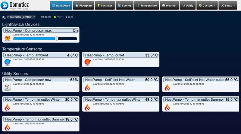
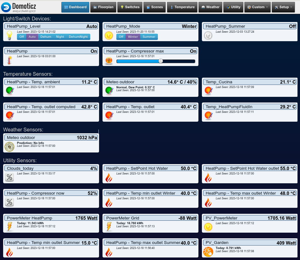
Wärmepumpen-Panel , das den aktuellen Stromverbrauch, die Photovoltaikleistung, Sollwerte, den Status usw. anzeigt. Das gesamte Panel ist sehr lang und enthält auch den Ventilstatus, Raumtemperatur und -feuchtigkeit usw. Es ist zu beachten, dass die Wärmepumpenleistung automatisch von einer Domoticz-Automatisierung (Skript) verwaltet wird, um den gesamten Strom aus der Photovoltaik zu verbrauchen .
Warmwasser-Panel mit einem Kessel mit integrierter Wärmepumpe. Einige der Bedienelemente sind direkt in die Wärmepumpe integriert, außerdem gibt es einige externe Sensoren.
Einbruchmeldeanlage mit 3 Betriebsmodi, Statusanzeige (um IP-Kameras anzuzeigen), Sirenen, einigen Lichtern, PIR- und Magnetkontaktsensoren.
Grundrisse (danke an Paolo Patt. für das Video)
Was Sie mit Domoticz tun können
Lichter: werden über Druckknöpfe zu bestimmten Zeiten EIN- und AUSGESCHALTET ( z. B. 25 Minuten nach Sonnenuntergang einschalten und 40 Minuten vor Sonnenaufgang ausschalten ). Dimmen und Farbwechsel .
Türklingel: Nimmt einen Schnappschuss von der IP-Kamera auf, wenn jemand klingelt, und sendet das Bild per Telegramm an eine Person oder eine Gruppe: Auch E-Mail und viele andere Benachrichtigungssysteme sind implementiert.
Tore, Fußgängertüren, Garagentore und Haustüren können per Fernzugriff (beispielsweise vom Smartphone) geöffnet werden : Wenn der Amazon-Lieferant klingelt und Sie nicht da sind, können Sie das Bild auf Telegram sehen und dann das Tor öffnen, damit er einfahren und die Waren für Sie ausliefern kann!
Wettersensoren : Außentemperatur, Luftfeuchtigkeit, Druck, Regen, Wind, Windrichtung usw. können überwacht und in Diagrammen aufgezeichnet werden
Überwacht Raumtemperatur, relative Luftfeuchtigkeit, CO 2 und verwaltet das Heiz-/Kühl-/Lüftungssystem auf intelligente Weise
Überwacht den Stromverbrauch/die Stromerzeugung vom/zum Stromnetz , sendet eine Warnung, wenn der Stromverbrauch einen Schwellenwert erreicht, bei dessen Überschreitung eine Stromabschaltung droht, und aktiviert/deaktiviert Geräte, um den Stromverbrauch zu optimieren.
Wenn Strom aus erneuerbaren Quellen verfügbar ist (z. B. Photovoltaik), kann die Wärmepumpe so gesteuert werden, dass sie den größten Teil der Energie aus erneuerbaren Quellen verbraucht.
Überwacht den Füllstand des Regenwassertanks für die Bewässerung von Gärten und Gemüsegärten
Verwalten Sie die Alarmsensoren (Magnetkontaktsensoren, PIRs, Radare usw.) und Sirenen vollständig , um ein voll funktionsfähiges und anpassbares Einbruchmeldesystem zu erhalten
Obwohl Domoticz auf vielen Plattformen funktioniert, darunter Windows und Mac, ist Raspberry eine gute Lösung, eine Single-Board-Computer-Hardware mit Quad-Core-ARM-MCU, die stabil und günstig ist und normalerweise weniger als 3 W verbraucht.
Normalerweise ist Raspberry mit einem Raspbian-Betriebssystem (Debian GNU/Linux für Raspberry) ausgestattet und unterstützt wie jedes Linux-Betriebssystem viele Dienste wie Web, DHCP, DNS, FTP, Samba, E-Mail usw. sicher und zuverlässig.
RockPI S
Dies ist ein sehr kleiner Single-Board-Computer mit Quad-Core-CPU, 512 MB RAM und sehr geringem Stromverbrauch: normalerweise 400 mW. Eine ideale Lösung für Domoticz, wenn ohne viele Skripte (Automatisierungen) gearbeitet wird, die viel CPU erfordern.
Domoticz- und Creasol DomBus-Module
Wir sind ein Elektronikunternehmen, das Systemmodule für die Hausautomation herstellt, die auf hohe Zuverlässigkeit und sehr geringen Stromverbrauch optimiert sind und mit zwei verschiedenen Firmwares erhältlich sind:
DomBus-proprietäres Protokoll, funktioniert mit Domoticz
Modbus-Standardprotokoll, funktioniert mit fast allen Heimautomatisierungssystemen
Creasol DomBus-Module und Domoticz
Welches Betriebssystem verwenden Sie für Domoticz?
Linux (Raspberry PI, Rock PI, NUC, PC, ....)? Sie können das Creasol DomBus-Plugin auf zwei Arten installieren:
mithilfe des Python Plugin Managers oder Domoticz Plugin Managers , sofern Sie ihn installiert haben: Dies ist ein Python-Plugin, mit dem Sie problemlos andere Python-Plugins installieren und aktualisieren können.
Windows: Geben Sie im Verzeichnis „Domoticz“ den Ordner „ Plugins “ ein (oder erstellen Sie ihn), erstellen Sie einen Unterordner „CreasolDomBus“ und fügen Sie die Dateien „ plugin.py “ und „CreasolDomBusProtocol.py “ ein, die Sie von https://github.com/CreasolTech/CreasolDomBus herunterladen können.
Starten Sie Domoticz neu und unter „Setup“ -> „Hardware“ finden Sie eine neue Creasol DomBus-Hardware: Fügen Sie eine Instanz hinzu, geben Sie einen Namen ein (z. B. „Dombus“), wählen Sie den seriellen Port aus, der an den RS485/USB-Konverter angeschlossen ist (oder den virtuellen seriellen Port, der an ein Netzwerk-/RS485-Modul angeschlossen ist) und klicken Sie auf die Schaltfläche „Hinzufügen“.
Wenn Sie ein neues DomBus-Modul anschließen, finden Sie ein neues Gerät im Domoticz-Schalterfeld : Wählen Sie es aus ( Schaltfläche „Bearbeiten“ ) und ändern Sie seine Adresse in eine eindeutige, indem Sie das Feld „Beschreibung“ des Geräts ändern und den Text „HWADDR=0x0001“ hinzufügen (setzen Sie die Adresse auf 1, wenn dies das erste Modul ist) oder eine Adresse Ihrer Wahl eingeben. Klicken Sie auf die Schaltfläche „Speichern“ und laden Sie dann das Schalterfeld (oder das Dienstprogrammfeld usw.) neu. Sie finden neue Geräte, die diesem Modul zugeordnet sind. Als nächstes werden die angeschlossenen Module auf die gleiche Weise angezeigt. Ebenso müssen Sie die Standardadresse in 0x0002, 0x0003 usw. ändern. Jedes Modul hat eine eindeutige Adresse! Domoticz fügt automatisch ein Gerät für jeden Modulport hinzu .
Außerdem können viele Modulanschlüsse auf unterschiedliche Weise konfiguriert werden. Beispielsweise kann ein digitaler Eingang auch als Wasser-/Gas-/Energiezähler, Doppeltaste (Auf-/Ab-Taste wird über einen einzigen Anschluss gesteuert), Temperatursensor NTC, analoger Eingang (zum Messen einer Spannung oder eines Widerstandswerts), Distanzsensor usw. konfiguriert werden. Mit Domoticz kann die Konfiguration durch einfaches Schreiben in das Feld „Gerätebeschreibung“ erfolgen .
Außerdem unterstützen DomBus-Module (mit DomBus-Protokoll) DCMD-Befehle : Ähnlich wie bei KNX ist es möglich, einen Port so einzustellen, dass verschiedene Geräte automatisch aktiviert werden . Beispielsweise wird bei kurzem Drücken einer Taste das Licht umgeschaltet (an dasselbe Modul oder an ein anderes DomBus-Modul angeschlossen), bei 1 Sekunde langem Drücken wird ein anderes Gerät eingeschaltet, bei 2 Sekunden langem Drücken wird etwas anderes getan und bei 4 Sekunden ... Es ist klar, dass sich auf diese Weise sehr, sehr einfach einfache Automatisierungen schreiben lassen, und sie funktionieren auch, wenn der Hauptcontroller (Domoticz) ausgefallen ist. Schließlich ist es mit DCMD-Befehlen auch möglich, Domoticz-Szenen/-Gruppen zu aktivieren .
Bei sehr komplexen Systemen ist es auch möglich, mehrere USB/RS485-Adapter (oder Netzwerk/RS485-Module) zu verwenden, um verschiedene Busse zu haben, z. B. einen für jede Etage, wodurch für jeden Bus ein DomBus-Hardware-Plugin aktiviert wird. Auf diese Weise funktionieren die anderen Busse weiter, wenn ein Bus nicht mehr funktioniert (z. B. wegen Wartungsarbeiten). In diesem Fall funktionieren DCMD-Befehle nur innerhalb desselben Busses: Es ist nicht möglich, Geräte in einem anderen Bus automatisch zu aktivieren, ohne den Domoticz-Controller zu durchlaufen.
Strong reliability, Very low latency, Very very low power consumption: these are the features offered by DomBus modules, to make your house a smart home!
Nowadays always is wireless, but WiFi modules consumes too much, Zigbee/Thread has a poor range and need several mesh nodes: in any case with wireless devices you can expect devices to become unreachable. Ethernet is much safe, but wiring is not easy: star connection with large switches to connect all devices.
To achieve the maximum reliability and very very low power consumption, DomBus modules use the industrial RS485 wired bus to communicate: with a 4 wires shielded cable (common alarm cable with 2*0.50mm² + 2*0.22mm² wires inside) it's possible to carry both data and 12Vdc power supply. RS485 can work with up to 1km of cable, using the terminating 100-150 Ohm resistors on the ends of the bus : you can find the terminating resistor in each DomBus module, and it should be enabled through the PCB jumper in the two furthest modules. RS485 allows connection with any network topology (star, linear, mixed), making it easy to connect multiple modules, obviously you need to install a thin cable!
Works locally (no cloud and internet connection is needed), no battery, no pain: zero latency and very strong security!
DomBus modules are really low power consumption, less than 15mW with no outputs active, so it's possible to supply dozens of modules with no problem. Also, DomBus31 module that has 8 relays, consumes only 600mW when all 8 relays are ON; DomBus36 module has 12 relay outputs consuming less than 750mW with all relays on; DomBus21 module has 3 latching relays with 15A capability (3kW), consuming only 15mW even with relays are ON! We believe that power optimization is important: many wifi modules consumes more than 1Watt each, but 1W means more than 8 kWh/year for each WiFi module!
How to build the home automation system
Choose a reliable power supply for the bus: we suggest to use a 13.5V power supply unit with lead-acid battery charge feature. Power supply should be strong enough to supply domotic bus, network switches and routers, IPCams and NVR, ... , so the whole system can work even in case of power outage.
Choose a low power domotic controller: for small system you can use Rock PI S , which consumes only 0.4W, or Raspberry PI that is powerful (more ram, higher CPU speed) that consumes 2.3W. Kits with ready to use operating system and software are available from store.creasol.it
Choose a reliable power supply for the domotic controller, if used: the best solution is a a DC/DC converter with Type-C or MicroUSB connector, supplied by the 13.5V power source, so the domotic controller is protected from blackout.
Connect the domotic bus data to a RS485/USB adapter, and supply wires to the 13.5V power supply through a fuse. Use RS485 cables or, alternatively, common alarm shielded cables: 2x0.22mm² for data and 2x0.5mm² for Vbus supply. Connect the shield to GND only on one side. If connection by wire is impossible, you can connect by RF/WiFi/LAN using the appropriate interface.
In any room where you have to measure temperature and humidity, place a DomBusTH module: it is very compact and can be mounted on a blank cover with a 3-4mm hole in the center. It also has red/green leds (that can be used for notifications, like alarm on/off, import/export power, ...), white led (that can be used for notifications and as blackout emergency light), 1x analog input to monitor Vbus voltage, 4x I/Os (that can be connected to switches, pushbuttons, dual buttons, buzzer, energy/gas/water meters with pulsed output, alarm sensors, ...) and 2x open-drain outputs (that can be connected to the DomRelay2 module to get 2 relay outputs to command lights, roller shutter motors, appliances, ...).
If you need to interface a gate or garage door, you can use DomBus23 module, that has 2x relay outputs (to send open/close/pedestrian commands), 2x low voltage optoisolated inputs (to be connected to photocell power supply or 12/24V light indicating the gate state), 1x 115/230V optoisolated input (to be connected to 230V flash lamp, if needed to get status from this output, or can be used to monitor power outages). Also, DomBus23 has 1x 12-24V 10A mosfet output (can be used to supply a 12/24V led stripe, with dimming function), 2x analog outputs 0-10V (can be used to regulate the heat pump power, valve, or other appliances with 0-10V input, as like as other led dimming modules), and 2x I/Os.
If you need several inputs for alarm sensors (magnetic contact sensors and PIRs), you can use the compact DomBus12 module that has 7x I/Os (configured as digital inputs, analog inputs, twinbuttons, counters, buzzer outputs, ...) + 2x open-drain outputs (that can be connected to external DomRelay2 module to get 2 relay outputs, or can be configured as digital inputs through PCB jumpers to have totally 9 inputs).
If you want to make a homemade alarm system and need more inputs and also some outputs, you can use DomBus37 module that has 12x low voltage inputs, 3 AC inputs (100-250Vac) and 3 relays outputs, or DomBus38 module that has 12x low voltage inputs, 4 SPDT relays, 2 relay and 1 AC input.
If you need several relay outputs, you can use DomBus31 module that has 6x relays with 5A 250V SPST capability and 2x relays with 10A 250V SPDT capability (terminal block with both normally-open and normally-closed outputs). This is very low power consumption module, that consumes less than 600mW with all 8 relays ON!
If you need more relays, we have DomBus36 module that has 12 relay outputs in 3 groups: 1 common + 4 relays for each group, to get easy and quick wiring, consuming less than 750mW with all 12 relays ON!
If you need to control high power appliances with up to 3kW power, you can use DomBus21 module: it has 3 latching relays with 15A capability, 1 AC input (to monitor 230V presence, and also as a zero-cross detector to switch ON/OFF relays preventing overcurrent and overvoltage) and 4 low voltage inputs (for pushbuttons, switches, meters, temperature probes, ...)
Use DomBusEVSE module to charge the electric car: you can select how much power to get from the grid, from 0% (use only photovoltaic power) to 100% (use all available power) preventing overloads and disconnections. This is a full features charging system: for example it has the EVMINVOLTAGE feature that permit to charge the electric vehicle with the minimum power needed to keep voltage below 253V (preventing solar inverter derating).
Use DomBus33 module to manage a light system that uses pushbutton switches that activate step-by-step relays: DomBus33 permits to know the status of the light and control the step-by-step relay coils to toggle, switch on and switch off lights, with the ability to have a button to switch all lights off (or a simple automation that switch off lights when alarm is activated in AWAY mode).
If you're renovating your house don't forget to:
install magnetic contact sensors on windows, doors, blinds, external and internal sirens, external PIRs or RF radars: using Domoticz, Home Assistant, ... it's possible to build a complete alarm system with full notifications (text, pictures, small videos) in Telegram
install at least one IP cam oriented to the main gate , so you can receive a picture in your smartphone (Telegram) when somebody push the door bell button,
do not install thermostats to control room temperature: it's much better to install temperature sensors in each room (DomBusTH module) and let the domotic controller to controls the heater or heat pump : in this way it's possible to overheat (in Winter) or overcool (in Summer) the house when extra power is available from photovoltaic
use DomBusEVSE to charge electric vehicles (DIY wallbox) and DomBusTracker2 to control a single or dual axis sun tracker in the garden.
For any questions please contact us by DomBus Telegram group https://t.me/DomBus , Whatsapp or by email to Diese E-Mail-Adresse ist vor Spambots geschützt! Zur Anzeige muss JavaScript eingeschaltet sein. : your questions and suggestions are really important and let us improve the documentation!
DomBus or Modbus protocol?
DomBus modules are provided with two protocols of your choice:
DomBus protocol, very powerful multimaster protocol that works only with Domoticz controller by installing its python plugin, and Home Assistant, OpenHAB, Node-RED, ... by using the DomBusGateway bridge (software daemon, Home Assistant App or hardware module). DomBus protocol permit to get zero latency and DCMD functions: commands exchanged between modules, like KNX®, that permit to make simple automations that work even if the domotic controller is OFF.
Modbus RTU standard protocol that works with almost any home automation system, and it designed for custom applications or to work with industrial systems.
Some application notes
Using DomBus modules with Domoticz
In Domoticz, install the Creasol DomBus plugin, if not already done, from GitHub or from Python Plugin Manager
Connect this DomBus module to the domotic controller by a simple RS485/USB adapter (the preferred reliable solution), or by a RS485/net module or radio interface . Please note that more DomBus modules can be connected together to the same bus. Also, it's possible to manage more DomBus buses, for example one for each floor. It's recommended to supply each bus at 13.8V, with a backup battery, to get a home automation system working even in case of blackout; protect the bus with a fuse (1A or more, depending how many devices are connected). Assure that termination resistor is connected/enabled in each bus end (two 120 Ohm resistors for each bus); DomBus modules already have a termination resistor that can be enabled by a solder iron.
Check in the Switches panel for the new device, edit it, and in the description field add the following "command" ,HWADDR=0x0101 or similar to program the module with a new, unique, address between 0x0001 and 0xfeff (hexadecimal format), then save
Reload the Switches panel: all device ports will be added automatically and will be ready to use.
DomBus modules with Home Assistant
You have three ways to get DomBus modules working with Home Assistant (or other controllers supporting MQTT with AutoDiscovery):
By using the DomBusGateway app (ready-to-use add-on for HAOS or HA Supervised)
Use the DomBusGateway system you prefer: DomBusGateway is a bridge between the DomBus network and any home automation system supporting MQTT; moreover, thanks to AutoDiscovery, all entities will be created automatically.
Enable MQTT integration in Home Assistant
Connect this DomBus module to the domotic controller (or DomBusGatewayPIS hardware) by a simple RS485/USB adapter (the preferred reliable solution), or by a RS485/net module or radio interface . Please note that more DomBus modules can be connected together to the same bus. Also, it's possible to manage more DomBus buses, for example one for each floor. It's recommended to supply each bus at 13.8V, with a backup battery, to get a home automation system working even in case of blackout; protect the bus with a fuse (1A or more, depending how many devices are connected). Assure that termination resistor is connected/enabled in each bus end (two 120 Ohm resistors for each bus); DomBus modules already have a termination resistor that can be enabled by a solder iron.
If more devices of the same type must be connected, it's recommended to modify the module address: connect DomBusGateway by telnet (port 8023) then type the commands showbus (list the modules attached to the bus) showmodule ff32 (specify the address of the module you wan to configure) setport 1 hwaddr=101 (to set the device hardware to the new, unique value 101: valid address from 1 to efff, hex format)
You'll find the new device, with that address, in the MQTT integration and in the dashboard, with all entities already available.
DomBus modules with Node-RED, OpenHAB, ioBroker and other system supporting MQTT
Please check previous section, dedicated to Home Assistant: DomBus devices can be managed by any system supporting MQTT by using the bridge DomBusGateway: a python daemon running in background, or a dedicated hardware (Rock PI S) running DomBusGateway software.
Systems that support AutoDiscovery automatically detect all entities (ports) of the DomBus module.
A telnet interface on DomBusGateway permits to make some customization, for example device hardware setting, port configuration, ...
Using DomBus modules with Modbus protocol
As said, DomBus modules are available in two versions:
supporting Modbus protocol: this is a standard master/slave protocol that can be useful in some cases, for example to manage relay outputs, inputs that do not change frequently, sensors, DomBusEVSE module (to build a EV charging station), DomBusTracker2 (to control a single/dual axis solar tracker), ...
supporting DomBus protocol: this is a proprietary protocol, low latency, that also permits to exchange commands between modules (called DCMD) to realize simple automations that work even in case that the domotic controller is down. This is the preferred protocol, expecially when alarm sensors are needed.
If Modbus firmware is needed, it's possible to configure DomBus modules using the proper Modbus registers: check the page of each module to list the Modbus registers.
We'd like to describe some solutions to measure the energy consumed and produced by the building using Domoticz home automation system and energy meters like DDS238 and SDM120, SDM230 (single phase), SDM630 (threephase).
Having information about the used/produced power is useful to correctly manage loads (or heating/cooling system, electric vehicle charging, ....) in the right way, maximizing the own-produced energy from photovoltaic plant.
Solution 1: interfacing any energy meter with pulsed output using a DomBus module
This solution works with any kind of energy meter with pulsed output.
Normally, energy meters have 1 or 2 pulsed opto-insulated outputs to send 1000, 1666 or 2000 pulsed every kWh imported and exported.
If DomBus modules are used in the home automation system, it's easy to configure one or two input ports as IN_COUNTER to measure the imported/exported power and energy.
The following schema shows a system using DomBus module, but what it's interested in this case is that it shows a Eastron SDM230 energy meter, with 2 pulsed outputs connected to the I/O ports IO8 and IO9 of module DomBus12 (but DomBus23, DomBus33 and DomBusTH can be used as well). This is a reliable solution: if Domoticz controller is stopped, DomBus module continues counting pulses up to 64k (equivalent to 32-64kWh) and when Domoticz resumes, the energy counter is restored correctly without loosing pulses.
Using DomBus12, DomBus23, DomBusTH, DomBus32 or DomBus37 it's very easy to read the pulses from energy meters, compute the instant power and get two devices in Domoticz that show the usage and return power, usage and return total energy and graphs. Below the instructions that refer to Eastron SDM230 energy meter: similar procedure for any other energy meter with pulse outputs, like DDS238 energy meter.
connect the pulse outputs to any available I/O, for example IO8 and IO9 for DomBus12, IO1 and IO2 for DomBusTH or DomBus23 or DomBus32 or DomBus37. The SDM230 common terminal block should be connected to GND (0V). Other energy meters may have output S0+ that should be connected to the DomBus I/O and S0- to GND.
configure Pulse1 output, on SDM230, as EXP kWh (check the manual to know how to do that); Pulse2 is pre-configured as IMP kWh (measure the energy imported from grid)
configure the Domoticz device connected to Pulse2: press Edit on that device, and replace in the Description field IN_DIGITAL or IN_TWINBUTTON (the default value) with IN_COUNTER,TYPENAME=kWh and save. Please note that kWh is CASE SENSITIVE! Now the device will be automatically moved to the Utility panel and configured as energy meter. Edit it again, write a name (for example PowerMeter_Import), and select Usage type.
if produced energy should be measured, configure the Domoticz device connected to Pulse1 as before: press Edit on that device, and replace in the Description field IN_DIGITAL or IN_TWINBUTTON with IN_COUNTER,TYPENAME=kWh,DIVIDER=2000 (where divider number correspond to the pulses/kWh of your meter) and save. Now the device will be automatically moved to the Utility panel and configured as energy meter. Edit it again, write a name (for example PowerMeter_Export), and select Return type.
In case of both import and export devices are created, it's needed to specify on Import device the Unit number of the Export device, and vice versa. So, select Setup -> Devices and write down the Unit number corresponding to Import (for example 98), and Export device (for example 99), then go to Utility panel, edit Import device and add to the description ,OPPOSITE=99 (Unit of the Export device) and save; edit Export device and add to the description ,OPPOSITE=98(Unit of the Import device) and save. In this way, when a pulse is received on Import device, the power on Export device will be immediately set to 0, and vice versa, when a pulse is received on Export device, the power on Import device will be set to 0.
Domoticz needs up to 5 minutes before updating the energy counter correctly.
Check the youtube video that shows the instant power shown on the web browser (Domoticz panel) every 2 seconds.
Solution 2 - Using DDS238-2 ZN/S (single phase) or DTS238-7 ZN/S (three phases) Modbus energy meters with DomBus modules
It's possible to connect up to 4 DDS238-2 ZN/S energy meters to a single DomBusEVSE module. DDS238-2 ZN/S have 2 terminal blocks with A and B signals (RS485 Modbus), so it's possible to connect together up to 4 energy meters to the A/B terminal block of DomBusEVSE module: in this way it's possible to measure, for each meter, import/export power, energy, voltage, frequency and power factor.
Values are updated every 5 seconds.
DomBusEVSE is a module designed to control an electric vehicle charging (Mode-3 EV charging station / wallbox). It supports up to 4 energy meters, single and three phases, providing imported energy and power, exported energy and power, active power (negative if power is fed to the grid), voltage, frequency and power factor.
DomBus34 is a module. It supports up to 4 energy meters, single and three phases, providing imported energy and power, exported energy and power, active power (negative if power is fed to the grid), voltage, frequency and power factor.
TODO: connection schema
Solution 3 - Using ESP8266 module (NodeMCU, Wemos, ...) with Eastron energy meters with ModBus RS485 interface
The energy meter is connected between the first circuit breaker and the circuit breakers used for each zone: in this way it measure the used/produced power globally.
Please choose the energy meter model that integrates the RS485/Modbus interface, so it's possible to connect to ESP8266 board through a RS485 to TLL converter so ESPEasy can read power (positive if used, negative if produced), voltage and other variables.
Lua scripts
Some LUA scripts for Domoticz are available, to manage the house power: in the Winter, they activates electric heaters automatically when exported power (from photovoltaic plant on the roof?) is greater than electric heater power. Similarly, any kind of device can be configured (e.g. dehymidifiers / dryers).
It also send an alert when power usage is above the max available power, to prevent disconnections from the electric grid (overcurrent protection).
Creasol DomBus devices are home automation modules that manage inputs, outputs and sensors, available with two protocols: DomBus proprietary protocol (works with Domoticz by using a python plugin, and also works with Home Assistant, Node-RED, OpenHAB, ioBroker and other systems supporting MQTT-AutoDiscovery protocol by using DomBusGateway software), and Modbus RTU standard protocol that works with Home Assistant, Node-RED and other controllers by using Modbus integration.
Actually we produce the following modules:
DomBusTH: Temperature + Relative Humidity sensors, red + green + white LEDs, 4 GPIO, 2 open-drain outputs, 1 analog input
DomBus12: 7 GPIO, 2 open-drain outputs (configurable also as inputs)
DomBus23: 2 relay outputs, 1 mosfet output (for 12-24V LED dimming or other DC loads), 2 analog outputs 0-10V, 2 GPIO, 2 low voltage opto-inputs (5-40V), 1 230Vac opto input
DomBus31: low power module with 6 N.O. relay outputs + 2 N.O./N.C. relay outputs
DomBusEVSE: EVSE module usable to build a smart wallbox (electric vehicle charging station)
DomBusTracker: stand-alone 2-axis solar tracker controller, that can be interfaced by Domoticz, HomeAssistant, Node-RED, OpenHAB, ioBroker, Modbus custom software, ...
Using DomBus modules it's possible to make a full domotic system: the following picture describe a real example of a house using Domoticz + DomBus modules to control:
full alarm system, with PIR and magnetic contact sensors on windows/doors/blinds
climate control (heating and cooling by heat pump) with optimizations to use the most energy from renewable (photovoltaic system on the roof)
ventilation control, disabling air renewal, in winter, when the wind blows from certain directions (to prevent combustion fumes from entering the house)
lights on/off control
230V sockets that can be enabled/disabled by smartphone
garden irrigation and rainwater tank level measure/control
door bell control: when someone ring the bell, send a picture to the smartphone by Telegram. Obviously, it's also possible to open the gate or pedestrian gate by smartphone
when presence/movement is detected outside, with the alarm enabled, grab a short 20s video from IPcam near the outdoor sensor and send video to Telegram.
electric vehicle charging station
single or dual axis sun tracker for optimized photovoltaic system
DomBusTH is a really powerful and cheap board, to be mount on a blank cover with a 4mm hole in the center, with a touch sensor (to have a virtual pushbutton) that measures emperature and humidity, and have 3 LEDs: red and green LEDs are used to notify alarm, ventilation or electricity power import/export status, and white led is used as night light and emergency light (in case of blackout). Also, it can be connected to piezo buzzer for sound alerts, pushbutton switches, and external relay module DomRelay2 to control 230V sockets or roller shutter motor.
Also, GPIO/input of DomBus modules can be connected to energy meter with pulsed output, to measure the current imported/exported power. As written above, it's possible to show the actual imported/exported power on RED/GREEN Leds of a DomBusTH module.
Although DomBus protocol is not a standard, this is the best solution because:
it's a multi-master protocol: all modules can be master and transmit. Instead, Modbus protocol is a master/slave protocol, and needs that a controller continuously poll all devices to know their states.
modules notify the controller as soon as a state changes (alarm input, pushbutton, counter/meter, temperature, ...), with less than 100ms latency
modules can communicate each-other to get small automation working even if the controller is OFF, as KNX does.
How to get DomBus + HomeAssistant working?
Install mosquitto or another MQTT broker : it's used to get home automation system communicating with all devices
Install MQTT integration on Home Assistant
Install DomBusGateway python software: it's used to communicate to DomBus modules by RS485 bus, and to HomeAssistant (or other controller) by MQTT AutoDiscovery. Configure the file dombusgateway_conf_local.py
Connect the DomBus module to the bus: you can immediately see a new device with the default hardware address of the DomBus module (for example ff38 for DomBus38)
Change the default address of the module to a unique address (in hex from 1 to efff, or from 1 to 9999) by * connect DomBusGateway in telnet: telnet localhost 8023 * select the bus, if system have more than one DomBus bus, with command showbus 2 to select bus number 2. Ignore if only 1 bus is used. * select the installed module, for example showmodule ff38 * change address to 3801, for example, with the command setport 1 hwaddr=3801
Now a new device will be available in Home Assistant, for the module with new address 3801
Repeat step 4 and 5 for all modules that should be connected, to form a reliable network of modules (inputs, outputs, sensors, ...) that can work even in case of blackout by supplying the bus using a power supply unit with 12V lead-acid battery.
Using DomBus modules with Modbus firmware
In case that DomBus modules are equipped with Modbus firmware, it's possible to use Home Assistant Modbus integration already available in HA. Modbus protocol is standard and well supported by Home Assistant as like as other systems (Node-RED, OpenHAB, ...).
DomBus36 is a simple module with 12 relay outputs, grouped in 3 groups to have an easier wiring: each group share the same common, so you don't need to make jumpers to connect the common wire (Line, Neutral, Ground or +12/24V) to all relays. Relays are protected from overvoltage and overcurrent, and module has a very low power consumption: less than 15mW with all relays OFF, and less than 750mW when all 12 relays are ON. Please compare with the power consumption of a Shelly, Sonoff, Denkovi or KMTronic module!
Using DomBus36 module with Home Assistant and Modbus protocol, already integrated in HA. The 12 ports (entities) are configured in the configuration.yaml file.
DomBus37, a versatile module with 12 low voltage inputs, 3 AC inputs and 3 relay outputs
DomBus37 is a versatile module integrating inputs, AC inputs (to sense 230V presence) and relay outputs. In the application note below the simplest configuration with Home Assistant.
Using DomBus12 to measure water tank level, temperatures, start irrigation and light, check alarm sensors
DomBus12 is a compact and cost effective module with 9 I/Os. Each I/O can be configured as button, switch, double-pushbutton (UP/DOWN pushbutton connected to a single port), counter, meter, NTC temperature sensor, distance sensor, buzzer, led, ...
Sometimes sensor or counter data registered by Domoticz in the database may be wrong due to bad measure or counters inited from a wrong value.
What to do?
Check the device chart with all values, and use shift+click on the bad values to cancel them from the database.
In case of counters, if you have to change the current energy value (or else), you have to:
1. Stop domoticz (service domoticz stop or other command)
2. Make a backup of domoticz.db database: (cp domoticz.db backups/domoticz_20231216.db or something else)
3. Connect to the database using the command sqlite3 domoticz.db
4. Modify the counter values in Meter_Calendar (or other table) using the following queries: .tables select * from Meter where DeviceRowID=1722 order by Date; update Meter set Value=Value-56000 where DeviceRowID=1722 and Date>='2023-11-28 21:10:00'; update Meter_Calendar set Value=Value-56000 where DeviceRowID=1722 and Date>='2023-11-28 21:10:00';
5. also, you have to modify the last value for that device with the sql query update DeviceStatus set sValue='6;518227.4281' where ID=1722;
Of course you have to use the right idx value corresponding to your device, and right values and date. The examples above are only examples. The step 5 is used to set the current value of the meter: your problem was that you updated the Meter and Meter_Calendar tables, but not the DeviceStatus tables, so when domoticz restarted, it continued to use the bad value. I hope this can be helpful for you!
How to export database backups in a external USB hard disk
If you're running Domoticz on a single board computer with SD or SSD memory, and you have an external hard disk connected by USB, to prevent the flash memory (that can be written only about 100 thousands times) I suggest to move the DOMOTICZ/backups directory on the external hard disk (that must be mounted at boot time, so it should be placed in /etc/fstab). The following commands permit to enter DOMOTICZ directory, create a domoticz dir in the external hard disk, move the domoticz backup on the hard disk and create a symbolic link to it:
I also suggest to disable the hourly database backup, because it takes several seconds where automations stop working. To do this it's sufficient to remove the hourly directory and create a file with the same name, so Domoticz will not be able to create hourly directory and will skip the hourly backup:
cd /mnt/USB/domoticz/backups rm -rf hourly > hourly
Wenn Sie die folgenden Anweisungen befolgen, können Sie eine Ladestation für Elektrofahrzeuge bauen, die den Stromverbrauch aus dem Netz überwacht, um Überlastungen und Unterbrechungen zu verhindern und außerdem nur Energie aus Photovoltaik zu verwenden. Das DomBusEVSE-Modul kann nach der Programmierung im Stand-Alone-Modus ohne die Notwendigkeit eines Domotic-Controllers betrieben werden .
Sie müssen wissen, was Sie tun: Sie müssen Kenntnisse über Leistungsableitung und elektrische Systeme haben. Sie müssen Elektrotechniker sein, um selbst eine Wallbox zu bauen!
Sie müssen außerdem über Computerkenntnisse verfügen und wissen, was ein Hausautomationssystem und das Modbus-Protokoll sind.
Das DomBusEVSE-Modul ist der EVSE-Controller, der die Kommunikation mit dem Bordladegerät Ihres Fahrzeugs für einphasiges und dreiphasiges AC-Laden ermöglicht: Wählen Sie die DomBusEVSE-Version für Ihren Bedarf:
mit proprietärem DomBus- Protokoll, funktioniert mit Domoticz ,
mit Modbus- Standardprotokoll, funktioniert mit Home Assistant , Node-RED , OpenHAB und vielen anderen Hausautomationssystemen.
Nachfolgend finden Sie die Diagramme für einphasige und dreiphasige Verkabelung : Sie benötigen mindestens einen 2P- oder 4P-RCCB (Schutz) und Schütz, das EV-Kabel und einen RS485/USB-Adapter (oder RS485/TCP). Die Komponenten sind in unserem Shop erhältlich , auch in KITs , aber da es sich um Standardkomponenten handelt, können Sie sie überall finden.
Es ist besser, 10-mm²-Kabel für 32 A und 6-mm²-Kabel für 16-A-Wallboxen zu verwenden, um die Verlustleistung der Kabel zu minimieren. Die Anschlüsse müssen regelmäßig überprüft werden, um sicherzustellen, dass die Schrauben gut angezogen sind, damit sich die Anschlüsse bei maximaler Ladeleistung nach 15 Minuten oder mehr nicht erhitzen!
Wenn Sie über ein Heimautomatisierungssystem mit einem an den Domotic Controller angeschlossenen Netzstromzähler verfügen , der die Netzleistung misst (negativ, falls dieser Strom ins Netz eingespeist wird), müssen Sie keinen weiteren Zähler an das EVSE-Modul anschließen: Erstellen Sie einfach eine einfache Automatisierung , die regelmäßig (alle 1–6 s) die aktuelle Netzleistung an das EVSE-Modul sendet.
Ein Leistungs-/Energiemessgerät zur Messung der Ladeleistung/-energie des Elektrofahrzeugs ist nicht unbedingt erforderlich, wird jedoch empfohlen. DomBusEVSE unterstützt DDS238-2 ZN/s (einphasig) und DTS238-4 ZN/S (dreiphasig).
RS485-Busse erfordern mindestens einen Abschlusswiderstand (100-150 Ohm), besser noch einen Widerstand an jedem Busende: Für den EVSE-Hausautomationsbus ist es möglich, den Widerstand durch Kurzschließen des Rb- PCB-Jumpers zu aktivieren. Für EVSE-Energiezähler ist der Widerstand bereits im EVSE-Modul aktiviert.
Die T-Wechselrichter der WVC-2000-Familie (WVC-1600, WVC-2400, WVC-2800) sind sehr schön und preisgünstig und in zwei Versionen erhältlich: mit Sub-1-GHz-Transceiver (benötigt eine DTU, um dieses Protokoll zu verwalten und in WLAN umzuwandeln). ) und WLAN, Verbindung zum Sensornetzwerk „Cloud Intelligence“. Wir empfehlen jedoch dringend, dieses Produkt auszulassen, weil:
Es ist nicht sicher : Trennen Sie es vom Netz (Stromausfall oder Ausschalten des RCBO), die erzeugte Spannung springt auf 285 V, fällt dann in 30 Sekunden auf 248 V ab und bleibt bis zum Sonnenuntergang bei 248 V! Dies ist nicht sicher, der Wechselrichter muss prüfen, ob 230 V anliegen, und bei einem Stromausfall die Produktion stoppen, um Stromschläge zu vermeiden.
Wechselrichter mit sehr niedrigem Wirkungsgrad : Da der Wechselrichter Gleichstrom- und Wechselstrom-Telemetriedaten an die Cloud Intelligence sendet, ist es einfacher, den Wechselstrom anhand des Gleichstrom-Leistungsverhältnisses zu berechnen, und er liegt unter 0,92 (8 % Verlust). Tatsächlich steigt die Wechselrichtertemperatur bei nur 600 W Ausgangsleistung und 30 °C Umgebungstemperatur auf 58 °C, was nicht gut ist
Sehr schlechter MPPT-Algorithmus : Beim Vergleich der Wechselstromleistung, die von 830-Wp-Modulen mit diesem Wechselrichter erzeugt wird, und einer anderen Photovoltaikanlage mit SolarEdge-Wechselrichter beträgt der Gesamtwirkungsgrad dieses Wechselrichters 0,815 im Vergleich zum SolarEdge-Wechselrichter.
Hoher Leckstrom : Aufgrund des Leckstroms, der höchstwahrscheinlich durch die hohen Kondensatoren entsteht, die im EMI-Filter mit der Erde verbunden sind, ist es zwingend erforderlich, das Gehäuse des Wechselrichters mit der Schutzerde zu verbinden.
Entdecken Sie unser Sortiment an Domotikmodulen für Smart Home!
Das folgende Video zeigt eine Präsentation einiger von Creasol entwickelter und hergestellter Domotikmodule, um ein zuverlässiges, einfaches und stromoptimiertes Hausautomationssystem zu erhalten.
Software oder vorkonfigurierter Computer, der ein oder mehrere DomBus-Netzwerke (Netzwerk von über einen Bus verbundenen Domotikmodulen) verwaltet und Daten per MQTT mit AutoDiscovery mit einem Domotik-Controller austauscht.
The script_time_selfconsumption.lua file, available at https://github.com/CreasolTech/domoticz_lua_scripts , permits to update 5 devices in Domoticz measuring the self-consumption and self-sufficiency of the building, when one or more power sources are available (photovoltaic on the roof, photovoltaic in the garden, wind turbine, ...)
The script will update the following utility meters:
TotalProduced energy/power: (the array POWERMETER_GENS in config_power.lua contains the list of meters measuring power for each plant)
Enter the GitHub project https://github.com/CreasolTech/domoticz_lua_scripts and download script_time_selfconsumption.lua config_power.lua, globalfunctions.lua and globalvariables.lua into the DOMOTICZ/scripts/lua directory.
The following variables should be defined in config_power.lua:
PowerMeterImport='PowerMeter Import' -- Meter measuring import power PowerMeterExport='PowerMeter Export' -- Meter measuring export power POWERMETER_GENS={'PV_PowerMeter', 'PV_Garden'} -- list of devices measuring power from renewable plants (PV on the roof, PV on the garden, wind, ...)
-- The following 5 devices have to be created manually (Setup -> Hardware -> Create virtual device) POWERMETER_USAGE='Power_Used' -- Electric+Counter virtual device (to be created manually) POWERMETER_PROD='Power_Produced' -- Electric+Counter virtual device (to be created manually) POWERMETER_SELF='Power_SelfConsumption' -- Electric+Counter virtual device (to be created manually) PERCENTAGE_SELF='Perc_SelfConsumption' -- Percentage virtual device (to be created manually) PERCENTAGE_SUFF='Perc_SelfSufficiency' -- Percentage virtual device (to be created manually)
Check the domoticz log for any errors, and wait at least 5 minutes to see the new devices charts.
Updating the database domoticz.db
The following operations are NOT RECOMMENDED because CAN DAMAGE THE DATABASE.
If you have months or years of data, and you want to import all data in the new meters, you can get information from the database, save in a CSV file to elaborate with a spreedsheet program, then add them to the database. ALWAYS MAKE A BACKUP OF THE DATABASE before each operation!
In my case, I have two solar photovoltaic systems, a powerImport device and powerExport device measuring the power from grid and power to grid. Domoticz is running in Linux OS. In the following instructions, comments describing each action are rapresented with #text...
cd /home/pi/domoticz   #enter domoticz directory
cp domoticz.db /home/backup/domoticz_202407011753.db   #make a backup of database
sqlite3 domoticz.db   #run sqlite client program
sqlite> .output /tmp/file1.csv
sqlite> SELECT * FROM Meter_Calendar WHERE DeviceRowID=105 ORDER BY Date; #105=idx of first solar meter
sqlite> .output /tmp/file2.csv
sqlite> SELECT * FROM Meter_Calendar WHERE DeviceRowID=1942 ORDER BY Date; #192=idx of second solar meter
Open file1 and file2 with libreoffice or other spreedsheet program, then merge the column by using the same date in the same row, then add a column with the sum of the two energies in each row, and another column with the counter value, as shown in the following picture.
where 2104 is the idx of the new POWERMETER_PROD value (you can get it entering the Utility panel in Domoticz, and clicking on Edit button on that device).
Save the file in /tmp/file3.csv then
sqlite3> .mode csv sqlite3> .import /tmp/file3.csv Meter_Calendar sqlite3> UPDATE DeviceStatus SET sValue="0;35732997" WHERE ID=2104;
The second line imports the file data in the existing table with day-by-day data of every meter device, the third line update the meter status with the current counter value. Replace 35732997 with the last couter value in the file3.csv + today energy, in Wh.
Check the POWERMETER_PROD chart: you should see the total produced power in the last days, months or years.
Now, get exported energy data from the PowerMeterExport device (idx=967 in my case):
sqlite> .output /tmp/fileExport.csv sqlite> SELECT * FROM Meter_Calendar WHERE DeviceRowID=967 ORDER BY Date;
then open fileExport.csv and compute, for each date, SelfConsumption=ProductionEnergy-ExportedEnergy, and import data with the commands
sqlite> .import /tmp/selfConsumption.csv Meter_Calendar sqlite> UPDATE DeviceStatus SET sValue="0;13673479" WHERE ID=2100;
where 2100 is the idx of the created POWERMETER_SELF device, and 13673479 is the last counter value + today SelfConsumption energy.
Calculate the selfConsumption_percentage=int(SelfConsumption*100/ProductionEnergy) and export a CSV file with the fields idx,perc,perc,perc,date
With percentage device you don't need to update the DeviceStatus table: that's needed only for counters. Export in a spreedsheet the imported power (from grid), then calculate the TotalUsedEnergy=SelfConsumption+ImportedEnergy, and finally calculate the SelfSufficiency_percentage=int(selfConsumption*100/TotalUsedEnergy); import all data in the same way explained above.
Verwendung eines Wasserdurchflusssensors mit DomBus-Modulen
Wasserdurchflusssensoren sind nützlich, um den Kalt- und Warmwasserverbrauch zu messen. Einige Wasserdurchflusssensoren basieren auf einem Hall-Sensor zur Messung der internen Rotordrehung und erzeugen Impulse von bis zu 100–200 Hz. Hall-Wasserdurchflusssensoren sind keine empfindlichen Sensoren, insbesondere wenn sie wie der auf dem Bild gezeigte aus Eisen bestehen. Wir empfehlen daher , Messgeräte mit der höchsten Empfindlichkeit zu wählen, z. B. 1–30 l/min, aus Messing. Beachten Sie, dass der Sensor 0 Impulse ausgibt, wenn die Durchflussrate unter 1 Liter pro Minute liegt! DomBus-Module können mit Hochgeschwindigkeitssensoren arbeiten, erzeugen bis zu 500 Impulse/Sekunde , sind für einen sehr niedrigen Stromverbrauch optimiert und verfügen normalerweise über viele vielseitige Ports, die als Eingänge, Ausgänge, Zähler, Sensoren usw. konfiguriert werden können.
Das Bild unten zeigt, wie DomBus37 mit einigen Temperatursensoren, Alarmsensoren, Wasserdurchflusssensoren und Strom-/Energiezählern verbunden wurde.
Wasserdurchflussmesser, Temperatursensoren, Energiezähler mit DomBus37 und Domoticz nutzen
Wenn DomBus-Module mit Domoticz verwendet werden (in diesem Fall das mit dem DomBus-Protokoll programmierte DomBus37-Modul ), müssen Sie Folgendes konfigurieren:
NTC Temperatursensoren (10k bei 25°C, B=3950) als IN_ANALOG,FUNCTION=3950 ;
Der Wasserdurchflussmesser ist als IN_COUNTER,A=0,0025 (400 Impulse pro Liter) mit dem Teilerparameter=1000 konfiguriert, um von Liter in m³ umzurechnen;
Strom-/Energiezähler (DDS238-2) als IN_COUNTER,TYPENAME=kWh,DIVIDER=2000
PLEASE CHECK THE ENGLISH VERSION TO GET THE UPDATED VERSION OF THIS PAGE!
The following application note shows how to measure the level of rainwater (or other liquid) inside a tank, using a waterproof ultrasonic distance sensor JSN-SR04T.
This solution works perfectly with Domoticz home automation system, a complete, free and open source software for domotic applications, using DomBus modules programmed with DomBus firmware.
Also, using the DomBus modules with Modbus firmware, works also with Home Assistant, Node_RED, OpenHAB and other domotic systems supporting the standard Modbus protocol.
The following graph displays the measured level of rainwater inside a tank: level decreases when water is used (during garden irrigation, for example) and increases during rains; below the connection diagrams of the ultrasonic distance sensor to the DomBus12 module .
The following DomBus modules support the ultrasonic distance sensor:
DomBusTH, with DomBus or Modbus firmware: 6 I/Os module with RGB leds, touch sensor and temperature/humidity sensors, supporting up to 5 distance sensors (IO1, IO2, IO3, IO5, IO6) + 1 trigger output (IO4) controlling all sensors (short the o4 PCB jumper to set IO4 port as output).
DomBus12, with DomBus or Modbus firmware: 9 I/Os module, supporting up to 6 distance sensors (IO1, IO2, IO3, IO4, IO5, IO6) + 1 trigger output (IO7) controlling all sensors (all triggers connected to IO7, that should be set as output by shorting the RO7 PCB jumper).
DomBus23, with DomBus or Modbus firmware: versatile module with different types of ports, supporting 1 distance sensor (IO1) + 1 trigger output (IO2) controlling the sensor: IO2 have to be set as output by shorting the RO2 PCB jumper.
DomBus32, with DomBus or Modbus firmware: 3 relay + 3 AC inputs + 5 I/O modules, supporting 4 distance sensors (IO1, IO2, IO3, IO4) + 1 trigger output (IO5) controlling all sensors: IO5 have to be set as output by shorting the RO5 PCB jumper.
DomBus33, with DomBus or Modbus firmware: 3 relay + 3 AC inputs + 5 I/O modules designed for lighting systems, supporting 4 distance sensors (IO1, IO2, IO3, IO4) + 1 trigger output (IO5) controlling all sensors: IO5 have to be set as output by shorting the RO5 PCB jumper.
DomBus33, with DomBus or Modbus firmware: 3 relay + 3 AC inputs + 5 I/O modules designed for lighting systems, supporting 4 distance sensors (IO1, IO2, IO3, IO4) + 1 trigger output (IO5) controlling all sensors: IO5 have to be set as output by shorting the RO5 PCB jumper.
Documentation for JSN-SR04T waterproof distance sensor
Using DomBusTH module to control up to 5 distance sensors
Connect the 5V power supply and GND to the distance sensor boards (they works also with 3.3V).
Connect IO1, IO2, IO3, IO5 or IO6 to the "echo" sensor output. In case of IO5 (that is factory configured to works as open-drain output), to use it as input port connected to the "echo" output, you have to open R05 (with a cutter) and short the RO5 (with a solder iron) PCB jumpers. The same for IO6.
Connect IO4 to the "trigger" sensor input. Also, short the "O4" pcb jumper to use this I/O port as output.
Configure (by software) IO4 (trigger) and IOx (echo) as DISTANCE (normally these ports are factory configured as digital inputs or outputs). Using Domoticz, just write in the description field of the sensor devices (both trigger and echo ports) the string ",DISTANCE" to set the port as distance sensor. In case of Modbus, program the address 255+portnumber to the value 13, corresponding to the DISTANCE sensor type.
The module returns the distance in millimiters, and is updated every 15s.
Using DomBus12 module to control up to 6 distance sensors
Connect the 5V power supply and GND to the distance sensor boards (they works also with 3.3V).
Connect IO1, IO2, IO3, IO4, IO5 or IO6 to the "echo" sensor output. In case of IO5 (that is factory configured to works as open-drain output), to use it as input port connected to the "echo" output, you have to open R05 (with a cutter) and short the RO5 (with a solder iron) PCB jumpers. The same for IO6.
Connect IO7 to the "trigger" sensor input. Also, short the "RO7" pcb jumper to use this I/O as output.
Configure (by software) IO7 (trigger) and IOx (echo) as DISTANCE (normally these ports are factory configured as digital inputs or outputs). Using Domoticz, just write in the description field of the sensor devices (both trigger and echo ports) the string ",DISTANCE" to set the port as distance sensor. In case of Modbus, program the address 255+portnumber to the value 13, corresponding to the DISTANCE sensor type.
The module returns the distance in mm, and is updated every 15s.
Domoticz configuration
Configure the trigger output as DISTANCE: go to Switches panel, select the trigger device (IO4 for DomBusTH, IO7 for DomBus12, IO2 for DomBus23, IO5 for DomBus32/33), and write DISTANCE in the Description field, then exit. The trigger port now can be optionally disabled from Domoticz, by enter Setup -> Devices panel, and clicking in the blue arrow to remove this device from the list
Configure the echo sensor output port, by selecting the corresponding Domoticz device (for example IO1), the writing in the Description field DISTANCE,A=-0.1,B=165 A and B are parameters used to convert the sensor output (distance in mm) to the desired unit format. In the example above, if the sensor output is 400mm and distance from sensor to the tank bottom is 165cm, the value displayed in Domoticz will be value=400mm*(-0.1)+165=165-40=125cm corresponding to the tank level (total high=165cm, distance from sensor to fluid level=40cm, level=125cm) Alternatively, setting DISTANCE,A=0.1,B=0 it's possible to get back the distance in cm (A divide the sensor output (in mm) by 10).
Modbus configuration
Configure the trigger output as DISTANCE: check in the module webpage the Modbus address for the trigger port, for example for DomBus12 IO7 the Modbus register address is 6; configure that port as DISTANCE ( set register address 256+6=262 to value 13 )
Configure the sensor output port as DISTANCE: check in the module webpage the Modbus address for the sensor port, for example the Modbus address of DomBus12 IO1 is 0; configure that port as DISTANCE ( set register address 256+0=256 to value 13 )
Every 15 seconds the distance value will be refreshed and can be read from the port address (reading address 0, in the example above).
Using Domoticz it's possible to supply a router through the normally-closed relay output (SPDT relay); so, normally power supply is applied to the router, but if internet connection goes down, after some seconds or minutes Domoticz remove the power supply, wait for 10s, and apply power supply again to restart the router.
This monitoring procedure is performed by a bash script that sends pings to two different hosts, and if they do not respond, after some seconds or minutes, sends a command to Domoticz to activate the relay output that remove power supply to the router.
First, check that 127.0.0.1 (and your network, if you prefer) are specified in the Domoticz panel Setup -> Settings -> Local Networks: in this way any connection to domoticz from the specified networks do not need authentication (no username and password is required). If you add your LAN, all devices from your LAN can enter domoticz without asking for username and password.
To install the bash script, copy and paste the following code into the raspberry/linux shell:
[code]#become root
sudo su
#download script
if [ `which wget` ]; then
  wget -O /usr/local/sbin/netwatchdog.sh http://docs.creasol.it/netwatchdog.sh
elif [ `which curl` ]; then
  curl -o /usr/local/sbin/netwatchdog.sh http://docs.creasol.it/netwatchdog.sh
else
  #wget and curl not installed: install now
  apt install wget curl
  wget -O /usr/local/sbin/netwatchdog.sh http://docs.creasol.it/netwatchdog.sh
fi
chmod 755 /usr/local/sbin/netwatchdog.sh
# prepare /etc/rc.local so it is sufficient to remove a # to let raspberry start the script at boot time
sed -i 's:^exit 0:#/usr/local/sbin/netwatchdog.sh >/dev/null 2>/dev/null \&\nexit 0:' /etc/rc.local
sed -i 's/amp;//' /etc/rc.local[/code]
Now, find the idx corresponding to the relay output: open the web browser to the Domoticz page, go to Setup -> Devices to list all installed devices. Look in the idx column to find the idx of the router power supply device.
Now, copy&paste the following commands in the raspberry shell to put the script in debug mode (variable DEBUG=1 : in this way the script will print several debugging messages on the console and reduce the timings to check the script easily), edit the script (you have to write the right idx in the variable ROUTER_RELAY_IDX, check other variables, and type ctrl+x to exit):
[code]#set DEBUG=1 in /usr/local/sbin/netwatchdog.sh
sed -i 's/^DEBUG=0\(.*\)/DEBUG=1\1/' /usr/local/sbin/netwatchdog.sh
#edit script
nano /usr/local/sbin/netwatchdog.sh[/code]
and finally start the script in debug mode (reset the router after only 20s of ping failures), writing some information in the console and other information in the logfile:
[code]/usr/local/sbin/netwatchdog.sh[/code]
Remove the internet cable or switch-off the router: you should see that ping returns 100% packet loss and after 20s the script send a command to Domoticz to reset the router. Type ctrl+c to terminate the script.
If it works, type the following commands to edit /usr/local/sbin/netwatchdog.sh setting DEBUG=0 and to modify /etc/rc.local so the script is executed at boot time:
[code]#set DEBUG=0 in /usr/local/sbin/netwatchdog.sh
sed -i 's/^DEBUG=1\(.*\)/DEBUG=0\1/' /usr/local/sbin/netwatchdog.sh
#and now let linux starting the script
sed -i 's:^#/usr/local/sbin/netwatchdog.sh:/usr/local/sbin/netwatchdog.sh:' /etc/rc.local[/code]
Now you have to reboot to let linux start the netwatchdog.sh script.
Perché questa pagina? In Italia la propaganda per il fossile imperversa: ricordiamo che l'Italia, nonostante muoiano prematuramente oltre 90 mila persone a causa delle polveri sottili, ogni anno versa circa 30 miliardi di euro in sussidi alle fonti energetiche fossili (2022): forse anche per questo c'è una insistente disinformazione che circola nei media e nei social.
Bando quindi alle chiacchiere da bar e veniamo alle auto elettriche!
Critiche ricorrenti ai veicoli elettrici
Dopo 8 anni bisogna cambiare la batteria!
Non è vero: di solito la batteria è garantita 7-8 anni con almeno il 70% di autonomia residua, e questo non significa che debba morire appena scaduta la garanzia. In gennaio 2021, prima di acquistare l'auto elettrica, leggevo di un taxista di Modena che aveva percorso con la propria auto elettrica oltre 400mila km, ed un'altra persona che ne aveva percorsi addirittura 630mila km. Beh, mi auguro di poter cambiare l'auto dopo 18 anni dall'acquisto, anziché tenerla finché avrò esaurito la batteria!
Non ci sono sufficienti colonnine di ricarica
Al momento in cui scrivo questa pagina, secondo https://www.motus-e.org/fake-news/ sul suolo nazionale sono presenti 33 mila punti di ricarica accessibili al pubblico (marzo 2023). Per avere un metro di comparazione, i distributori di benzina in Italia sono circa 21 mila, mentre gli impianti di distribuzione del metano sono fermi a poco più di 1.400 (Dati EAFO). La rete delle infrastrutture per la ricarica pubblica in Italia è peraltro in continuo e costante ampliamento.
Aggiornamento gennaio 2025: sono installate in Italia oltre 64 mila colonnine, per un parco auto elettriche circolante di 300 mila unità circa: una colonnina ogni 5 auto!
Il problema sono le batterie perché usano metalli rari
Informazioni del 2023: mentre i telefoni e piccoli dispositivi attualmente utilizzano batterie Li-NMC (Litio, Nichel Manganese Cobalto) le quali hanno un'elevata densità di potenza (e sono quindi compatte), le auto elettriche si stanno orientando verso la tecnologia LFP (Litio Ferro Fosfato) che hanno una densità minore ma costano anche meno, non contenendo il cobalto. Mentre il Ferro è il metallo più abbondante sulla crosta terrestre, il Litio è il quarto metallo in ordine di abbondanza, quindi sono componenti tutt'altro che rari, tant'e' che lo stesso litio, presente nella quantità di 6-9kg per ogni auto, dopo il picco di costo dd fine 2021 ora sta diminuendo il suo prezzo in quanto sono state aperte nuove fonti di approvvigionamento.
Il problema delle batterie è lo smaltimento
Per le auto è fondamentale che la batteira abbia una elevata efficienza. Ma si stima che dopo 10-15 anni la batteria di un'auto possa diventare un punto critico (autonomia ridotta del 20% rispetto all'autonomia iniziale): in tal caso, oppure nel caso di smaltimento di un'auto, la batteria può essere impiegata come accumulo statico per case o altre strutture. Ad esempio lo stadio di Amsterdam è coperto da pannelli fotovoltaici e impiega numerose batterie delle prime Nissan Leaf rottamate (2012, ...) per l'accumulo di energia. Dopo il riuso (quindi dopo 20 anni o più) potranno comunque essere riciclate al 95%, ovvero i minerali saranno recuperati interamente per generare nuove batterie o nuovi prodotti.
Le auto elettriche sono più pesanti ed inquinano di più perché consumano più pneumatici
E' vero che normalmente si ha un consumo superiore di pneumatici, dovuto più che altro al comportamento del guidatore che spesso tende a sfruttare maggiormente l'elevata prestazione del motore elettrico in termini di coppia (accelerazione). Uno studio di Science Direct confronta le emissioni di auto a combustione interna con auto elettriche, stabilendo che la minore emissione di PM10 delle elettriche considerando freni e pneumatici. in quanto queste ultime utilizzano molto raramente i freni privilegiando la frenata rigenerativa (utilizzando il motore elettrico per rallentare l'auto ricaricando la batteria).
Costo chilometrico più alto rispetto al diesel
Ci sono colonnine veloci (150kW o più di potenza) il cui costo a consumo è veramente alto, 0.89€/kWh, ma bisogna essere anche un po' furbi: ci sono le tariffe flat! Acquisti un "abbonamento" e in un mese hai N kWh di energia che puoi ricaricare a tariffa fissa, a prescindere dal tipo di colonnina. Se li finisci prima del tempo, acquisti un nuovo "abbonamento". Funzionano come le ricaricabili, ma poi si rinnovano ogni mese se non vengono disattivate.
Prendiamo la tariffa più svantaggiosa: 0.40€/kWh. Con 1kWh si percorrono circa
5km in autostrada, a 130km/h => 8€/100km
7.5km in extraurbana => 5,35€/100km
Come vedi i costi sono decisamente inferiori rispetto al costo chilometrico per un'auto diesel o ibrida!
Il futuro è l'auto ad idrogeno
L'auto ad idrogeno è un'auto elettrica che, anziché avere la batteria, ha una cella combustibile.
Essendo che il processo di produzione dell'idrogeno "verde" ha un rendimento del 50-60% e il rendimento della cella combustibile è di gran lunga inferiore. Il risultato è che il costo a km di un'auto ad idrogeno è 3 volte quello di un'auto elettrica. Ma allora perché si parla tanto di idrogeno verde nella tassonomia dell'Europa? La produzione di idrogeno verde (da fonti rinnovabili) viene attualmente concepita come sistema di stoccaggio di energia nel momento di maggior produzione per l'utilizzo
nell'industria chimica, ad esempio per la produzione di ammoniaca
nella produzione di e-fuels, ovvero combustibili sintetici da impiegare in futuro in aerei e navi.
Produzione di idrogeno per la conversione in energia elettrica? NO, non conviene.
Esempio: autobus Solaris Urbino Hydrogen: ha una cella combustibile da 70kW, una batteria al titanato di litio da 29kWh, e con una carica di idrogeno da 37.5kg ha un'autonomia di 350km. Con il costo finale dell'idrogeno a 13.7€/kg (stazione di rifornimento di Bolzano, realizzata con 9.5 milioni di euro di cui 5 milioni di € di fondi europei), il costo per percorrere 350km risulta di 510€, 145€/100km. Il costo dell'idrogeno diminuirà con il tempo. Facendo un confronto, l'autobus elettrico Iveco E-Way, con batteria da 350kWh, ha un'autonomia di 570km ed un costo di 19€/100km (calcolato con tariffa di ricarica 0.31€/kWh corrispondente ad un abbonamento Enel X-Way).
Allora il futuro sono i biocarburanti!
Solo per soluzioni estreme dove è richiesto un alta concentrazione di energia che le batterie non possono garantire. Un ettaro di terreno coltivato a ricino per ottenere biocarburante consente di ottenere all'anno 46MWh di energia equivalente. Un ettaro di parco solare fotovoltaico produrrebbe in un anno 625MWh di energia elettrica, quindi la produzione di biocarburante non è conveniente. Fonte
Un altro studio che confronta la produzione di biodiesel (che comunque è un inquinante, producendo durante la combustione ossidi di azoto, benzoapirene e polveri sottili, tutti cancerogeni): * Con 1mq di suolo posso coltivare colza per produrre biocarburante necessario a percorrere 2km * Con 1mq di pannello fotovoltaico posso produrre energia elettrica per percorrere 900km Fonte: https://www.vaielettrico.it/biocarburanti-vs-elettrico/
Ad inquinare sono le navi e gli aerei
Si, ma in misura molto inferiore rispetto al traffico merci su gomma e soprattutto al traffico passeggeri.
Fake news sui veicoli elettrici smentiti dal dirigente del Consiglio Nazionale delle Ricerche di Bologna
Due video in cui vengono date informazioni chiare e scientifiche:
Vige il pensiero comune sulla pericolosità d'incendio delle auto e autobus elettrici, nonostante che i dati reali siano completamente opposti.
Su 100mila auto, il rischio più alto vale per la auto ibride; per le auto a benzina/diesel/gpl/metano è la metà di quelle ibride, e il rischio di incendio per le auto elettriche e meno di un centesimo rispetto alle ibride. Questi sono i fatti, anche se le chiacchiere da bar a volte dicono altro.
Costi di esercizio di auto elettriche, ibride, gpl a confronto
Nel link seguente sono riportati i costi a km delle auto, rilevati dall'ACI, in base a quanti km si percorrono annualmente. I costi si riferiscono ad un'auto di proprietà, ed i costi vengono calcolati in modo standardizzato. Nel caso di auto elettriche, si considera la ricarica fatta alle colonnine pubbliche. https://www.vaielettrico.it/costi-di-esercizio-a-confronto-elettriche-ibride-gpl/
Informazioni utili
La potenza si misura in Watt, o migliaia di Watt (1kW=1000W), ... L'energia in Joule, Wh (corrispondente alla potenza di 1W per un'ora di tempo), kWh (corrispondente a 1kW di potenza per la durata di un'ora), ... L'unità di misura kW/h non ha senso e non esiste!
La capacità della batteria viene in genere misurata in kWh: una batteria da 50kWh ha la possibilità di fornire una potenza di 50kW per un'ora di seguito, prima di scaricarsi completamente, oppure una potenza di 20kW per 2 ore e mezzo (se vai in autostrada a 130km/h probabilmente consumi 26kW, quindi avrai autonomia poco inferiore a 2 ore, ovvero 250km). Se devo caricare la batteria a 6kW di potenza, il tempo di ricarica dallo 0 al 100% sarà almeno di 50kWh / 6kW = 9h (dividiamo sia le cifre che le unità di misura!). Analogamente, il tempo di ricarica dal 30% all'80% (metà capacità, ovvero 25kWh) sarà di circa 5 ore.
Al punto precedente ho scritto "almeno", perché il processo di ricarica non ha rendimento al 100%: c'è un'elettronica di controllo da alimentare, una pompa di calore per il raffreddamento della batteria (in estate), perdite sul convertitore AC/DC e PFC, perdite sui cavi... il rendimento nella ricarica varia molto a seconda della potenza (migliora con potenze alte) e potrebbe aggirarsi sull'85-90%. Teniamo quindi presente che per ricaricare l'auto dissipiamo il 10-15% di energia in calore, quindi anche i tempi di ricarica sono il 10-15% superiori rispetto alla formuletta del punto 2.
Auto ibride e auto elettriche: due mondi molto diversi, e lo vedi sollevando il cofano. Un'auto mild-hybrid, full-hybrid e peggio ancora una plugin-hybrid hanno il cofano strapieno di componenti (che possono rompersi e che richiedono manutenzione periodica). Se apri invece il cofano di un'auto elettrica dentro trovi molto poco e ampi spazi vuoti. L'auto elettrica non richiede cambi d'olio, filtro aria, filtro carburante. Non ha frizione e spesso non ha il cambio (solo modelli sportivi hanno in genere un cambio automatico a 2 marce). Nell'auto elettrica devi cambiare il filtro abitacolo, ogni 30mila km circa, e i pneumatici. Neanche le pastiglie dei freni si cambiano, in quanto si utilizza quasi sempre la frenata rigenerativa.
Benefici economici di un'auto elettrica: oltre alla riduzione del costo chilometrico, i tagliandi sono praticamente una formalità, non si paga bollo per 5 anni, e dopo i 5 anni si paga 1/4 del bollo calcolato su una "potenza termica" (quella riportata in libretto) bassissima: ad esempio la mia auto ha una potenza di 150kW, ma nel libretto di circolazione è riportata una potenza termica di 29kW. Praticamente dopo i 5 anni pagherò un importo irrisorio di bollo (ma questo è un dato attuale: in futuro le cose possono cambiare!).
Meglio un accumulatore grande (tanta autonomia, a costo e peso maggiori) o un accumulatore più piccolo (meno autonomia, ma costo e poso inferiore)? A parte il costo, minor peso significa minor consumo di pneumatici. Inoltre una maggior capacità di batteria implica quasi sempre un maggior tempo di ricarica, quindi quando capiterà di fare un viaggio molto lungo bisognerà fare più soste ma probabilmente più brevi rispetto ad un'auto con autonomia superiore. Ho pianificato un viaggio di 1100km da Pieve di Soligo (Veneto) a Santa Maria di Leuca (Puglia) attraverso il sito https://www.abetterrouteplanner.com : con Kia Niro (con batteria da 64kWh, 450km autonomia, ricarica a max 77kW) mi basta fare 5 ricariche impiegando 3 ore 21 minuti di ricarica. Con una Peugeot e208 (con batteria da 50kWh, 340km di autonomia, ricarica a max 100kW) devo fare 7 ricariche impiegando solo 2 ore e 55 minuti. Batterie grandi consentono di avere grandi autonomie, ma richiedono tempi di ricarica più lunghe a parità di potenza. Quindi il fattore determinante nell'auto è la potenza massima di ricarica, e nei viaggi lunghi conta molto una buona programmazione delle ricariche: la potenza di ricarica è massima quando la batteria è scarica, e man mano che si ricarica la potenza deve necessariamente diminuire per non rovinare la batteria (non si deve superare la tensione massima consentita), quindi la soluzione più intelligente è ricaricare quando la batteria è intorno al 10% terminando la ricarica intorno all'80% o meno.
La ricarica domestica o al lavoro è certamente la soluzione più comoda: quando l'auto è parcheggiata si ricarica. Il sistema EVSE presente nel sistema di ricarica consente di specificare al caricatore di bordo nell'auto la potenza massima che può assorbire in quel momento. Si possono utilizzare dei cavi con presa schuko per caricare l'auto a 8-10-16A (da 1.5 a 3kW circa): è la soluzione più economica, lenta e bisogna stare attenti a non oltrepassare il limite di potenza contrattuale per evitare i distacchi, in quanto i cavi di ricarica non hanno un sistema per verificare la potenza prelevata dalla rete. Si possono usare anche wallbox che misurano la potenza prelevata dalla rete elettrica: in questo modo la wallbox potrà specificare dinamicamente la potenza massima che l'auto potrà prelevare al fine di evitare distacchi e minimizzare il tempo di ricarica, oppure stabilendo quanta potenza al massimo prelevare dalla rete. Ad esempio, se ho il fotovoltaico e stabilisco che la wallbox potrà prelevare al massimo 0 Watt dalla rete, utilizzerò solo energia rinnovabile dal fotovoltaico per caricare l'auto. Se ho il contatore da 5kW e imposto nella wallbox una potenza massima di 5500W, utilizzerò la massima potenza disponibile per la ricarica e questa verrà variata in base ai consumi istantanei della casa (forno, lavatrice, eccetera) per non superare mai la potenza che ho impostato.
Importanza di non caricare a bassa potenza per non sprecare energia: nel seguente video viene mostrato come varia il fattore di potenza quando si ricarica un'auto. I caricatori di bordo lavorano male a bassa potenza (lavorano in modalità discontinua, con un peggioramento dell'efficienza), pertanto è bene ricaricare sempre ad almeno 4kW. Per misurare l'efficienza "indicativa" di ricarica bisogna: 1. eseguire una ricarica dell'auto, possibilmente a corrente costante e con un bassa corrente (ad esempio 10A) , partendo da un SoC basso fino ad un SoC alto, misurando l'energia consumata. Nel caso si utilizzi una wallbox fai-da-te con DomBusEVSE, basta impostare EVMaxCurrent = 10 ed eseguire la ricarica con EVMode=100% 2. Efficienza = Capacita netta batteria * (SoC finale - SoC iniziale) / 100 / Energia utilizzata in ricarica Ripetere dopo qualche giorno la ricarica, partendo dallo stesso SoC iniziale (o simile), misurare l'energia, e calcolare l'efficienza con la formula del punto 2.
Ricarica pubblica: ci sono due tipi di colonnine, AC (in corrente alternata) e DC (in corrente continua). Le colonnine di ricarica in AC forniscono una corrente alternata, a 230V monofase o 400V trifase, che verrà convertita in corrente continua dal caricatore a bordo auto (On Board Charger). Solitamente gli OBC nelle auto hanno una potenza massima di ricarica pari a 7, 11 o 22 kW. Le colonnine AC possono essere già fornite di cavo per il collegamento dell'auto (tethered), ma la maggior parte ne è sprovvista ed in questo caso bisogna munirsi di un cavo AC Type-2 (salvo eccezioni) da 11 o 22kW secondo la potenza massima del proprio OBC. Per ricaricare la batterie con potenze (e quindi velocità) maggiori, bisogna collegare l'auto ad una colonnina di ricarica DC, che integra tutto il sistema di conversione da corrente alternata trifase a corrente continua (in modo da bypassare l'OBC dell'auto) per caricare la batteria secondo le indicazioni fornite dal Battery Management System presente nella batteria. In sostanza, l'auto comunica alla colonnina DC la percentuale di carica, la tensione massima e la corrente massima di ricarica, che variano in funzione alla temperatura e allo stato di carica seguendo un certo profilo di carica, e la colonnina fornisce energia in base a tali parametri. Ci sono colonnine DC a 25, 40, 50, 75, 100, 110, 150, 250, 350, 400kW: quelle con potenza superiore a 100kW vengono anche definite HPC, e sono in fase di installazione anche megawatt chargercon l'obiettivo di fornire potenze di ricarica ancora superiori, adeguate ad auto supersportive e soprattutto ai mezzi pesanti. Il grafico sottoriportato mostra la curva di potenza di una batteria, che risulta massima quando la batteria è scarica per poi diminuire quando la batteria supera il 70-80% di carica: questo è uno dei motivi per cui, nei viaggi molto lunghi conviene eseguire ricariche brevi fino al 70-80% piuttosto che voler raggiungere per forza il 100% di ricarica. Ricaricando la batteria al 100% inoltre si perde la possibilità per i primi km di sfruttare la frenata rigenerativa, in quanto la batteria non avrebbe la possibilità di accumulare energia essendo già carica completamente.
Esercizi per capire cos'è la potenza e cos'è l'energia.
Esercizio1: La POTENZA si misura in Watt. Ad esempio, il computer Raspberry PI4 (molto usato in domotica) consuma 2.3W, quando ha un carico di lavoro CPU basso. Quanta ENERGIA consuma il Raspberry in 1 anno? Energia=potenza * tempo, quindi 2.3W * (24x365) ore = 2.3*24*365 W*h=20148 Wh ovvero 20.148 kWh Si moltiplicano i numeri, ma si moltiplicano anche le unità di misura!
Esercizio2: In casa ho una batteria da 15kWh (capacità batteria = energia che può essere stoccata): se ho un esubero di potenza dal fotovoltaico di circa 2kW e la batteria è completamente scarica, quanto tempo mi serve per ricaricarla?
Come prima, Energia = Potenza * Tempo => Tempo = Energia/Potenza=15kWh/2kW = (15/2) kWh/kW = 7.5h In realtà impiegherà un po' di più in quanto il rendimento del sistema non è 100%.
Come ricaricare il veicolo elettrico alle colonnine pubbliche
Consiglio di scaricare l'app tariffev oppure un altro comparatore che consente di visualizzare la mappa delle colonnine disponibili e, per ciascuna di esse, conoscere l'app ed abbonamento con il prezzo più vantaggioso: la registrazione a tariffev è gratuita, ed il comparatore funziona anche dal browser web all'indirizzo https://tariffev.it .
Ad esempio, in agosto 2026 ad una colonnina EnelXWay da 22kW, il prezzo a kWh migliore è di 0.39€/kWh di notte e 0.54€/kWh usando l'app EVDC in modalità pay-per-use. Chi ha necessità di ricaricare spesso a questo tipo di colonnine durante il giorno potrà invece trovare economico l'abbonamento usando l'app A2A e-moving per caricare a 0.42€/kWh.
In questo caso, in una colonnina Plenitude da 110kW si può utilizzare l'app EVDC pagando 0.53 o 0.56€/kWh, oppure A2A e-moving in abbonamento a 0.42€/kWh. Altre app risulteranno più costose.
L'immagine mostra la tariffa applicata dal gestore EnBW utilizzando la propria app su stazioni HPC da 400kW: 0.51€/kWh in modalità pay-per-use, oppure 0.34€/kWh con abbonamento pagando 11.99€ ogni mese.
Come funziona il pagamento? Esistono le seguenti modalità:
Attraverso app su smartphone: bisogna registrarsi, inserendo i propri dati per la fatturazione del costo di ricarica ed i dati della propria carta di debito/credito. Alcune app consentono la gestione di un wallet, ovvero si ricarica il proprio conto virtuale ad esempio con 50€, e si utilizza quel credito per il pagamento delle ricariche godendo a volte di alcuni benefici: sconto sulla tariffa, oppure carta RFID in regalo, ... Alternativamente può essere eseguire il pagamento con la carta ad ogni ricarica, in questo caso verrà prenotato l'addebito di circa 50€ per iniziare la ricarica, che poi viene restituito dopo aver terminato la sessione di carica.
Attraverso RFID, in formato tessera o portachiavi, che è possibile acquistare o ricevere gratuitamente dai gestori: in questo caso la ricarica inizia e termina avvicinando la card alla colonnina, senza necessità di utilizzare l'app sul telefono.
Plug&Charge: è un sistema in fase di consolidamento che consente alla colonnina di ricarica (mediante un lettore presente nel connettore) di leggere un tag RFID presente sull'auto al fine di identificare il conto associato all'auto da cui prelevare l'importo di ricarica. E' il sistema più semplice e immediato da utilizzare, può funzionare solo su colonnine tethered ovvero che includono il cavo di ricarca, ed al momento è abilitato su poche colonnine e supportata da pochi tipi di auto.
Carte di debito o credito con pagamento stile distributore "self service".
Come pianificare un viaggio per sapere quando e dove ricaricare
Prima di un lungo viaggio vale la pena utilizzare un pianificatore per verificare quante ricariche sono necessarie, e dove. Ovviamente si può poi decidere di ricaricare dove si vuole, a seconda dell'orario e degli impegni, sfruttando le pause pranzo, visite turistiche, eccetera.
Un pianificatore molto utilizzato è ABRP , disponibile sia in app sia nel web: si definisce il tipo di veicolo utilizzato, luogo di partenza e arrivo, ed il sistema fornisce indicazione sul percorso e luoghi consigliati per la ricarica.
Quanto costa percorrere con l'auto elettrica 15mila km in un anno?
Dipende da quanto si paga l'energia elettrica e come si ricarica. L'immagine fornisce in sintesi il caso reale (non estremo) di ricarica prevalentemente durante il giorno (le giornate in estate sono lunghe, e si può ricaricare anche nel weekend) e disponibilità di un impianto fotovoltaico sul tetto, senza accumulo, il costo nel 2022 per percorrere 15mila km, riscaldare e raffrescare casa, far funzionare lavatrice, lavastoviglie, 2 frigoriferi, 1 congelatore, eccetera, è stato di negativo (ovvero il corrispettivo per la vendita dell'energia è stato superiore alla somma delle bollette elettriche e delle ricariche dell'auto eseguite alle colonnine pubblichedi cui 64€ per la ricarica alle colonnine pubbliche).
L'elettrificazione di casa e della mobilità è certamente un ottimo investimento: oltre alla riduzione dei costi, il beneficio economico è impagabile. Immagina di uscire per una passeggiata e non sentire la puzza di smog dovuto al trasporto e al riscaldamento a legna/pellet!!!
Come riportato nell'immagine, l'impianto fotovoltaico è l'artefice del cambiamento (verso un mondo meno inquinato) e del risparmio, ma hanno contribuito in maniera significativa anche l'auto elettrica e l'impianto domotico, utilizzando il software free Domoticz che attraverso uno script controlla la pompa di calore in modo da privilegiare il consumo nei momenti in cui l'elettricità costa meno e il rendimento risulta migliore.
Aggiunge alcune considerazioni: va benissimo l'impianto fotovoltaico a SUD d'inverno, se si usa la pompa di calore: la maggior parte dei consumi avviene nei mesi di dicembre/gennaio in cui ci sono poche ore di luce ed in cui il sole sorge a sud-est e tramonta a sud-ovest. Al contrario, nei 6 mesi caldi, il sole sorge a est e tramonta a sud: in questo caso il fotovoltaico su due falde rivolte a est e ovest consente di avere produzioni anche di prima mattina e in tardo pomeriggio, quando l'energia da fotovoltaico scarseggia ed i costi risultano più alti, contribuendo quindi sia a stabilizzare la rete sia ad avere una migliore remunerazione evitando il "picco di mezzogiorno" in cui ci sarà presto un eccesso di produzione elettrica. Il seguente grafico mostra l'andamento del prezzo (linea rossa) e dell'energia richiesta dall'Italia ora per ora, stimata per domani. Normalmente, nei giorni lavorativi, il prezzo sale al mattino (quando c'e' tanta richiesta di energia e ci sono tanti impianti fotovoltaici "stupidi" che impiegano l'energia per ricaricare l'accumulatore), e poi alla sera quando viene meno l'energia dal fotovoltaico; nelle belle giornate di sole, da aprile a ottobre, si può invece osservare un calo dei prezzi nelle ore pomeridiane (quando c'e' tanta produzione fotovoltaica e gli accumulatori sono carichi).
Il seguente grafico mostra l'andamento dei prezzi orari dell'energia in una giornata di weekend soleggiato, sabato 27 maggio 2023: si può notare come l'elevata produzione da fotovoltaico induca una drastica riduzione dei prezzi, a dimostrazione che le energie rinnovabili contribuiscono a ridurre il costo dell'energia. Sarebbe tuttavia opportuno che l'energia venga pagata dal consumatore in base al PUN orario, come avviene in Danimarca, affinché l'utente sia protagonista della stabilizzazione della rete: nel caso specifico sarebbe infatti opportuno che le auto elettriche vengano caricate quando il PUN è basso ovvero quando c'e' un eccesso di produzione.
Consiglio: nel caso di fotovoltaico rivolto a est e ovest è possibile installare 8kW circa di pannelli fotovoltaici collegati ad un inverter da 6kW (proprio perché non c'e' il picco di produzione). Meglio comunque sarebbe un tracking solare in grado di garantire una produzione quasi costante durante il giorno: maggior informazioni nella pagina in inglese con alcuni esempi sul tracking solare
Quali sono i consumi di una casa con riscaldamento/raffrescamento con pompa di calore e impianto radiante?
Ho fotovoltaico senza accumulo, e non sono contrario all'accumulo a prescindere. Più avanti penso di installare un piccolo accumulo per superare le ore serali in cui il costo è alto (essendo alti i consumi serali). Sono di Treviso, ho impianto da 7.2kWp sul tetto, su falde a est e ovest, che d'inverno rende come un 4.5kWp a sud. Riscaldo casa con pompa di calore, e nei mesi critici (dicembre/gennaio) il PV produce circa 4-10kWh/giorno e devo importare circa 30-40kWh al giorno. In questo caso le batterie non servono, soprattutto perché ho la pompa di calore che, grazie all'impianto domotico autocostruito, insegue i consumi del fotovoltaico (se produce molto, aumenta i suoi consumi). Negli altri periodi importo circa 4-5kWh al giorno: di notte la PDC non funziona, e d'estate raffresco il pavimento di giorno in modo da accenderla solo quando il fotovoltaico produce. Nel 2022 l'energia elettrica per alimentare e riscaldare casa, e percorrere anche 15mila km con l'auto elettrica, mi è costata meno di zero (ho guadagnato 117€ grazie alla remunerazione dell'energia immessa in rete). Quindi, per le mie esigenze, posso dire che:
* la maggior parte di energia viene importata d'inverno, e qui l'accumulo non serve a nulla a meno che tu non abbia un fotovoltaico di potenza esagerata che produce a mezzogiorno molto più di quanto consumi la PDC
* se ottimizzi l'uso degli elettrodomestici (accendendoli di giorno) e puoi ricaricare l'auto di giorno, ti basta un accumulo che copra il tuo fabbisogno notturno, che in genere è basso
* se puoi caricare l'auto solo di notte puoi pensare ad un accumulo più grande, ma tieni presente che stoccare e recuperare energia non è un processo senza perdite!
* l'auto elettrica si ricarica bene durante la pausa pranzo in cui la potenza dal fotovoltaico è massima. Nei mesi invernali la ricarico invece di notte.
Comunque sto valutando la possibilità di installare un accumulo da 6-10kWh per migliorare l'autoconsumo da marzo a ottobre, consapevole che i vantaggi non saranno economici bensì di sistema, nel senso che ridurrò l'impatto di casa sui consumi dalla rete.
Energia prodotta dal fotovoltaico sul tetto: Treviso, 2700Wp verso est + 4500Wp verso ovest
Energia importata dalla rete (fotovoltaico 7.2kWp, no accumulo, ampia casa A4 con pompa di calore)
Energia immessa in rete
Articolo pubblicato su VaiElettrico, 2025-01-04
Abito con mia moglie in provincia di Treviso, ho una casa singola di circa 250mq del 1992 che è stata ristrutturata 7 anni fa per avere un migliore isolamento termico (cappotto termico esterno) e per non utilizzare più il gas come fonte primaria di energia termica: ho infatti due pompe di calore, una per il riscaldamento (da 8kWt, consuma al massimo 3kW) ed una per l'acqua calda sanitaria, un impianto fotovoltaico sul tetto da 7.2kWp con inverter da 6kW, ed un contratto energia elettrica 100% rinnovabile con potenza di 5kW (potenza disponibile 5500W, oppure 6350W per max 2 ore ogni 4). Ho inoltre una Kia eNiro del 2021 con accumulatore da 64kWh netti. Ho schematizzato nell'immagine l'energia prodotta, importata, autoconsumata, i relativi costi, eccetera.
E' un bilancio provvisorio in cui ho stimato al ribasso il rimborso GSE (che in realtà dovrebbe essere superiore) per l'energia immessa in rete, e l'importo della prossima bolletta relativa all'energia elettrica di dicembre. Ho inoltre riportato i grafici dei consumi mensili della pompa di calore per il riscaldamento e raffrescamento, e l'energia mensile utilizzata per ricaricare l'auto, suddivisa poi in energia proveniente dal fotovoltaico ed energia proveniente dalla rete. Si può notare come in Pianura Padana sia molto più alto il fabbisogno energetico in inverno per il riscaldamento domestico, rispetto al raffrescamento estivo. In questa situazione le ricariche dell'auto in inverno avvengono utilizzando quasi esclusivamente energia dalla rete in quanto tutta l'energia prodotta dal fotovoltaico viene utilizzata nel mio caso dalla pompa di calore. D'estate invece l'auto risulta un'ottima soluzione non solo per viaggiare in modo economico (l'energia dal sole costa di solito dai 6 ai 12 centesimi al kWh, nel senso che se non ricaricassi l'auto tale energia immessa in rete verrebbe retribuita dal GSE), ma anche per stabilizzare la rete: in particolar nel mese di maggio, quando l'irraggiamento solare è forte e le temperature sono basse, spesso l'energia dagli impianti fotovoltaici tende a superare l'energia consumata, portando l'inverter solare a ridurre la potenza immessa in rete per non oltrepassare la tensione di 253V (230V + 10%): in queste situazioni sarebbe auspicabile che venissero utilizzate le auto come sistema per ridurre la tensione di rete accumulando l'energia che altrimenti sarebbe persa. Sempre per rimanere in tema, durante l'anno si sono spesso verificati dei periodi in cui il costo orario dell'energia (all'ingrosso) risultava quasi nullo: questa situazione si verificava in particolare nei weekend dei mesi di maggior produzione con temperature miti, oppure in periodo autunnale quando erano in corso importanti perturbazioni nell'Europa centrale con forti produzioni dagli impianti eolici. Anche in questo caso sarebbe auspicabile ricaricare l'auto, per sfruttare l'energia a basso costo, cosiccome sarebbe utile che anche i clienti domestici pagassero l'energia in base al prezzo orario, anziché alle fasce orarie, al fine di migliorare la stabilità della rete consentendo di consumare energia a prezzi agevolati nelle ore in cui è maggiormente disponibile e ridurre i consumi nelle ore di punta (prima mattina e sera). Le condizioni di prezzi favorevoli saranno sempre più disponibili in futuro, anche se l'Italia sta affrontando con lentezza la transizione energetica rispetto ad altri paesi europei: infatti se in Europa nel 2024 il costo medio dell'energia elettrica è scesa del 16% rispetto al 2023, in Italia osserviamo un progressivo aumento dei prezzi in quanto dipendiamo ancora troppo dal gas. Quando finalmente avremo anche noi una discreta capacità eolica e fotovoltaica, avremo anche noi i prezzi dell'energia negativi o azzerati come succede spesso in altri paesi europei nelle situazioni favorevoli per eolico o fotovoltaico! Termino con un parere relativo all'accumulo domestico, che ritengo superfluo ed economicamente sconveniente quando la pompa di calore è gestita in modo ottimizzato (inseguendo la produzione del fotovoltaico), raffrescando casa attraverso l'impianto a pavimento, e le ricariche all'auto possono essere fatte anche di giorno. Da aprile a ottobre l'energia importata dalla rete per il funzionamento di casa risulta mediamente inferiore ai 5kWh, corrispondenti a 1.3€ al giorno. Se avessi un accumulo potrei quindi risparmiare 1.3€ * 200 giorni = 260€ a fronte di un mancato introito dalla vendita di energia di 5kWh * 200 giorni * 1.15 (perdite per caricare e scaricare l'accumulo domestico * 0.10€/kWh = 115€, quindi avrei un beneficio di 260-115=145€ all'anno. Ma quanto sarebbe il tempo di rientro per l'installazione di un accumulo statico da 10kWh se il beneficio (sovrastimato) è di 145€ all'anno? Per il bene dei cittadini della Pianura Padana, auspico in un cambio di mentalità da parte del Governo al fine di consentire l'installazione di nuovi parchi eolici offshore al Nord, installazione di parchi fotovoltaici con tracking per avere una maggior produzione durante le prime ore del giorno e il tardo pomeriggio, ed una maggior coscienza da parte di tutti i cittadini riguardo i temi ambientali: viviamo in uno dei territori più inquinati, cerchiamo di utilizzare le nuove tecnologie quando dobbiamo cambiare caldaia e auto! Serviranno tanti anni, ma quando avremo finalmente smesso di bruciare combustibili fossili e legnosi, potremo finalmente arieggiare casa senza il problema della puzza dovuta alle polveri sottili che ogni anno causa la morte di almeno 60mila italiani. Spero che le informazioni riportate siano abbastanza comprensibili e possano essere utili a chi vuole valutare i benefici economici (oltre a quelli ambientali!) offerti dal fotovoltaico e dall'auto elettrica.
Consigli: che interventi fare e tempi di rientro
1. se non ti produci energia, la devi acquistare. L’energia elettrica costa molto, perciò l’impianto fotovoltaico si ripaga in pochi anni, grazie anche alla detrazione fiscale. 2. se produci l’energia e poi la disperdi, non hai fatto un grande affare: in particolare la casa va coibentata. Se hai un sottotetto non abitato, isolarlo posando dei pannelli XPS diventa una scelta mooolto conveniente e fai-da-te. Se hai un sottotetto non agibile, c’e’ la soluzione dell’insufflaggio di materiale isolante (palline di carta, o nel caso si abbiano caminetti/stufe a biomassa, fiocchi di lana di roccia o vetro). 3. il cappotto termico costa molto, ma per case datate come la mia è indispensabile per avere un basso consumo energetico d’inverno e poter quindi utilizzare una pompa di calore per il riscaldamento. In alternativa si possono rivestire internamente tutte le pareti. 4. il riscaldamento a pavimento è un altro elemento essenziale… chi acquista una casa che non ha ci pensi: se vuoi togliere il pavimento vecchio, installa anche l’impianto a pavimento. In alternativa si può installare anche un impianto radiante a soffitto, che funziona benissimo d’estate, un po’ meno d’inverno (quando ti siedi a tavola sentirai probabilmente le gambe fredde). Soprattutto l’impianto radiante a pavimento ti consente di accumulare energia evitando nelle mezze stagioni ed in estate di accendere la pompa di calore di notte (quando il fotovoltaico non produce). 5. Sempre per chi deve ristrutturare casa, consiglio vivamente l’installazione della ventilazione meccanica controllata (VMC), eventualmente con chiller per deumidificare. E’ una soluzione ottima per avere il ricambio d’aria necessario a non avere muffa in casa ed avere aria fresca. D’estate può essere utilizzato per raffrescare e deumidificare l’aria (per cui non serve installare degli split in giro per casa).
Alcune CONSIDERAZIONI SUL FOTOVOLTAICO
1. avere le falde a est e ovest come nel mio caso va benissimo in estate, ma va male in inverno in cui il sole sorge a sud-est e tramonta a sud-ovest 2. per chi intende installare il fotovoltaico, raccomando di installare più pannelli possibili, perché il fabbisogno energetico aumenterà sempre e ampliare l’impianto un domani potrebbe essere molto più costoso che installare subito più pannelli. Chi è in monofase ha il limite di 6kW per l’inverter, e considerando che d’estate fa caldo ed i pannelli rendono meno, chi ha una falda a sud può installare sicuramente moduli per almeno 7.5kWp, chi ha le falde a est e ovest può installare anche 9kWp. Verificate con il vostro tecnico! 3. considerate gli ombreggiamenti che potete avere soprattutto in inverno, con il sole basso: se avete camini, alberi, o l’antenna TV con i pannelli sotto, problemi con piccioni sporcaccioni, valutate la possibilità di installare moduli fotovoltaici con ottimizzatori (solaredge, huawei, tico, …) in modo da avere sempre la massima produzione anche in caso di ombreggiamenti, oppure microinverter con MPPT per ogni ingresso. 4. i tempi sono maturi per lo storage domestico, che potete sempre installare facilmente più avanti se avrete optato per un inverter che supporti l’accumulo. Scegliete un inverter senza ventola (indice di maggiore efficienza). 5. Non avendo alcuno storage non so bene le caratteristiche dei vari prodotti, ma tenete presente che la conversione DC/DC per caricare la batteria (quindi inverter ibrido in grado di caricare la batteria partendo dalla tensione dei pannelli fotovoltaici) è più efficiente della conversione AC/DC (ricarica batteria a partire dai 230Vac, ovvero quello che fanno gli inverter retrofit e i Tesla Powerwall), quindi in teoria è meglio dotarsi di inverter ibrido per un futuro accoppiamento ad una batteria.
Quanto produce un inseguitore solare a 2 assi?
Questi i risultati comparativi in Veneto, in una giornata autunnale, fra un inseguitore a due assi controllato dal nostro controller DomBusTracker e un impianto fotovoltaico sul tetto, orientato in parte a est e in parte a ovest.
Come viene remunerata l'energia immessa con lo scambio sul posto?
Il rimborso GSE può essere calcolato, all'incirca, nel seguente modo:
minimo(Energia immessa, Energia importata) * (prezzo zonale quartorario * coefficiente_perdita + CUS) = minimo(Energia immessa, Energia importata) * (circa 0.10 * circa 1.052 + circa 0.0652) valori relativi al 2024
Esempio: immetto in rete 3000kWh e prelevo dalla rete 5000kWh Valore rimborsato = 3000 * (0.1052 + 0.0652) = 511€ da cui va sottratto il costo di gestione GSE, che dipende dalla potenza dell'impianto.
Quanto consuma l'auto elettrica in montagna?
In salita consuma, in discesa ricarica. La disponibilità di una grande batteria consente di poter immagazzinare molta energia, a differenza delle auto ibride o ad idrogeno.
Ad esempio a febbraio 2022 ho fatto un viaggio di piacere sulle Dolomiti venete/trentine. Salito in cima al Passo Pordoi (2239m SLM) lo stato di carica della batteria era 59%. Da li sono sceso a Canazei, Moena, risalito al Passo San Pellegrino, Falcade, Agordo, Trichiana, e risalendo verso il Passo San Boldo, a circa 400m SLM lo stato di carica era ancora al 59%. In sostanza ho percorso 106km sfruttando l'energia accumulata scendendo dal Passo Pordoi.
E' possibile autocostruirsi un sistema di ricarica / wallbox che si integri con la domotica?
Si, bisogna ovviamente essere abbastanza esperti di elettronica/informatica/impianti elettrici.
Ci sono diversi moduli EVSE in commercio che controllano la ricarica del veicolo e si integrano con sistemi domotici attraverso collegamento WiFi, LAN o RS485. Creasol produce un modulo, ad uso sperimentale, che supporta i protocolli DomBus e Modbus RTU, e può essere utilizzato con qualsiasi sistema domotico opensource (Node_RED, HomeAssistant, ioBroker, OpenHAB, Domoticz, ....).
Contratti di fornitura energia elettrica con tariffa basata sul prezzo zonale orario
Questo è quanto fornisce DeepSeek. Da verificare, e sicuramente manca l'offerta 100% rinnovabile Duferco Pianetablu.
In Italia, alcuni fornitori di energia elettrica offrono tariffe "dynamic pricing" o "a prezzo variabile orario", che si basano sul prezzo zonale orario (o sul PUN, Prezzo Unico Nazionale) invece di applicare un prezzo fisso o una media mensile.
Ecco i principali fornitori che propongono tariffe di questo tipo:
1. Illumia – Tariffa "Miglior Prezzo" (ex Next Energy)
Come funziona:
Prezzo dell'energia allineato al PUN (Prezzo Unico Nazionale) in tempo reale con aggiunta di una componente fissa (spread).
Bolletta calcolata sul consumo effettivo nelle diverse fasce orarie (F1, F2, F3).
Vantaggi:
Conveniente se consumi energia nelle ore più economiche (es. di notte o nei weekend).
Il prezzo dell’energia cambia ogni ora/giorno/mese in base al mercato elettrico (GME).
Se hai un contatore smart, puoi sfruttare i prezzi più bassi (es. di notte o nei weekend).
Se invece hai un contatore tradizionale, il fornitore applica una media per fascia oraria (F1, F2, F3).
Conviene?
✔ Sì, se:
Hai un contatore smart e puoi spostare i consumi nelle ore più economiche.
Vuoi pagare un prezzo trasparente e legato al mercato.
❌ No, se:
Preferisci la stabilità di un prezzo fisso.
Non vuoi rischiare rialzi improvvisi in caso di crisi energetiche.
Energia rinnovabile in Italia
Collegamenti HVDC
Terna, il gestore dell'infrastruttura di rete di trasmissione italiana ha in cantiere, a partire dal 2023, di installare due reti dorsali HVDC per portare 2GW di potenza dal Sud Italia e isole verso il Nord. Spesa complessiva 11 miliardi di euro [Fonte]. HVDC sono collegamenti ad 500-600kV in corrente continua, quindi utilizzano due cavi conduttori, offrendo una perdita di circa 3% ogni 400km. Richiede delle costose stazioni di conversione AC/DC e DC/AC per la conversione in trifase e il collegamento quindi alla rete HVAC esistente (trifase a 115kV, 220kV o 380kV).
Parchi eolici offshore
Sono installazioni di turbine eoliche al largo della costa, su pali fissati sul fondale (se fondale basso) o su piattaforme galleggianti ancorate al fondale. I vantaggi delle installazioni offshore sono:
ridotto impatto visivo: a 20km o più dalla costa si intravedono appena
maggiore velocità del vento e minor turbolenze, dovute alla superficie piatta
maggiore disponibilità di vento
Attualmente (2023) hanno un costo (a parità di potenza) superiore rispetto alle installazioni onshore (in terra ferma) dovute al costo della piattaforma galleggiante ed ancoraggio. Facendo un paragone con il punto precedente, con 9 miliardi di euro sarebbe possibile installare parchi eolici offshore per una capacità di 3GW (magari in alto tirreno o adriatico) da collegare direttamente alla rete elettrica del Nord Italia. Forse sarebbe una soluzione più vantaggiosa rispetto a quella di installare tutto al Sud e dover investire capitali enormi per poi interconnettere il Sud al Nord, dal momento che il Nord attualmente richiede almeno 10GW di potenza rinnovabile.
Produzione annua in relazione alla velocità del vento
Il sito web di Energy Hunters risulta molto ricco di informazioni relative all'eolico. Interessante è anche la caratteristica degli aerogeneratori, avvero la producibilità annua di energia in funzione della velocità del vento:
La potenza aerodinamica varia con il cubo della velocità, ma ci sono molti aspetti da dover tener presente fra cui la capacità dell'aerogeneratore di variare l'inclinazione della pala per ottimizzare la produzione e mettersi in sicurezza in caso di elevate ventosità.
Fotovoltaico
Efficienza delle diverse tecnologie fotovoltaiche in relazione allo sviluppo (clicca per scaricare PDF ad alta risoluzione).
Biogas, biocarburanti
Alcune informazioni utili sull'efficienza di produzione di biogas e biocarburanti tratti dal video https://youtu.be/f-2qcqxKOy0 :
1 ha di mais consente di produrre 15MWh di biometano
1 ha di colture zuccherine/amilacee consente di produrre (in climi favorevoli come il Brasile) 6000 L di bioetanolo, ovvero 6.6MWh
1 ha di colture oleaginose consente di produrre 1000 kg di biodiesel, corrispondenti a 10MWh di energia
1 ha di fotovoltaico consente di installare da 500kWp a 1.5MWp a seconda della tipologia di installazione, con una producibilità che varia da 600MWh a 900MWh in Pianura Padana. In questo caso vi sono altri vantaggi rispetto ai biocarburanti: non si usano pesticidi, fertilizzanti e altri inquinanti, non è richiesta l'irrigazione e consumo di acqua, e viene consentita la coltivazione sotto i pannelli (agrivoltaico) con un ridotto irragiamento (e quindi consumo d'acqua).
Domoticz ist ein plattformübergreifendes Hausautomatisierungssystem, das dank seiner Programmierung in C++ sehr kompakt und schnell ist. Es ermöglicht die Erstellung komplexer Automatisierungen, beispielsweise zur Steuerung einer kompletten Alarmanlage oder einer Wärmepumpe.
Wir bieten eine schnelle Lösung zur Installation eines vorkonfigurierten Raspbian-Images für Raspberry Pi 3, 4 und 5 an, das mit der neuesten Domoticz-Software ausgestattet ist und so konfiguriert ist, dass der MicroSD-Flashspeicher erhalten bleibt (der Flashspeicher kann nicht mehr als 10.000 Mal sicher beschrieben werden) und ein wöchentliches Backup exportiert wird, das im Problemfall leicht wiederhergestellt werden kann .
Dieses Image wurde sowohl auf Raspberry Pi 3- als auch auf Raspberry Pi 4-Hardware getestet und verwendet die neueste Raspbian-Distribution.
Wenn Sie dieses Image auf eine microSD-Karte flashen, können Sie Ihre Domoticz-Geräte sofort über die Weboberfläche konfigurieren.
Extrahieren des Bildes auf eine microSD-Karte
Sie benötigen eine Linux-Distribution, wget, sfdisk, fsarchiver und eine microSD-Karte (oder SSD) mit mindestens 16 GB Speicherplatz.
Geben Sie in der Bash-Shell die folgenden Befehle ein:
Funktioniert sowohl mit Raspberry Pi 4 als auch mit Raspberry Pi 3
Raspbian + eine aktuelle Version von Domoticz
Optimiert zur Reduzierung von Schreibvorgängen auf dem Flash-Speicher: /tmp und /var/log befinden sich im RAMFS, nicht auf der SD-Karte, und der Swap-Speicher ist deaktiviert. Temporäre Domoticz-Dateien werden in /tmp und nicht auf der SD-Karte gespeichert, wodurch die Speicherlebensdauer verlängert wird.
Firewall mit iptables/netfilter, die durch Bearbeiten der Datei /usr/local/sbin/myfirewallpi.sh konfiguriert werden kann.
Backup, das automatisch ein inkrementelles Backup der geänderten Dateien erstellt; einmal pro Woche ein vollständiges Backup und einmal pro Monat ein Image erstellen; das Backup kann einfach auf eine angeschlossene USB-Festplatte oder ein NAS (FTP oder CIFS) exportiert werden.
Domoticz ist teilweise mit einigen Geräten konfiguriert und das Creasol Dombus-Plugin ist bereits installiert (Domoticz-Plugin zur Verwendung von Creasol DomBus-Geräten, die über einen RS485-Seriellbus an den Raspberry Pi angeschlossen sind).
Zugriff auf und Konfiguration des Raspberry Pi mit dem programmierten Image
Dies sind die Standardanmeldeinformationen für dieses Image: Linux-Benutzer: pi , Passwort: arangingenni Linux-Benutzer: root , Passwort: geriandallse Domoticz-Benutzer: domoticz , Passwort: creasol
Es wird empfohlen , diese Standardpasswörter zu ändern!
Wenn Sie Raspberry Pi mit diesem Image starten, bezieht er seine Netzwerkkonfiguration von Ihrem DHCP- Server (Router). Sie können ihn dann über den Browser unter einer URL wie http://192.168.1.123:8080 erreichen ( überprüfen Sie Ihren DHCP-Server, um die Raspberry Pi zugewiesene IP-Adresse zu ermitteln , oder führen Sie einen Netzwerkscan Ihres LANs durch). Wenn Sie sich mit Raspberry Pi aus den Netzwerken 192.168.*.*, 172.16.*.* oder 10.*.*.* verbinden, ist keine Authentifizierung erforderlich . Außerdem ist der SSH-Dienst aktiviert , sodass Sie als Benutzer pi oder root eine sichere Shell (mittels SSH, Putty oder einem anderen SSH-Client) aufrufen können.
Wie man ein Image von einer Raspberry-SD-Karte erstellt
Wir haben das Bash -Skript raspberry_domoticz.sh (siehe oben) geschrieben , mit dem sich eine Kopie des Raspberry-Speichers auf einem USB-Laufwerk speichernund außerdem eine neue SD-Karte mit dem Inhalt eines gespeicherten Images erstellen lässt .
Dies ist nützlich, weil:
Flash-Speicher sind nicht unbegrenzt beschreibbar : Normalerweise kann jede Flash-Zelle bis zu 10.000–100.000 Mal beschrieben werden. Das vorgeschlagene Image ist optimiert, um die Anzahl der SD-Karten-Schreibvorgänge zu begrenzen.
Es ist immer ratsam, ein Backup des laufenden Raspberry Pi zu haben , damit im Problemfall das System aus einem alten Image wiederhergestellt werden kann.
Vielleicht müssen Sie eine vorhandene SD-Karte klonen und die Images auf Ihrem PC oder NAS speichern.
Merkmale:
Die Bilder sind komprimiert ... es ist doch dumm, ein 16 GB großes Bild für eine fast leere 16-GB-SD-Karte zu haben!
Images können auf SD-Karten unterschiedlicher Größe wiederhergestellt werden , sodass es möglich ist, dasselbe Image sowohl für 32-GB- als auch für 8-GB-SD-Karten zu verwenden.
Das Erstellen und Wiederherstellen eines Images geht im Vergleich zu anderen Systemen sehr schnell .
Dieses System funktioniert leider nicht unter Windows, aber... wer nutzt heutzutage noch Windows? Alles geht doch in Richtung Linux! Android basiert auf Linux. Raspbian basiert auf Linux. Ihre Router, Access Points und Fernseher verwenden höchstwahrscheinlich ein Linux-Betriebssystem! ;-)
Klicken Sie hier, um das Skript raspberry_domoticz.sh herunterzuladen, speichern Sie es in einem ausführbaren Verzeichnis auf Ihrem Linux-System (z. B. /usr/local/sbin) und erteilen Sie ihm die Ausführungsberechtigung. Führen Sie raspberry_domoticz.sh aus und folgen Sie den Anweisungen, um ein komprimiertes Image von der Raspberry-SD-Karte zu erstellen. Dies funktioniert auch im Live-Modus, direkt vom laufenden Linux-System aus, mit hoher Erfolgswahrscheinlichkeit.
Wollen Sie mehr?Präsentation des äußerst zuverlässigen DomBus.
Häufig gestellte Fragen (FAQ)
Einige nützliche Befehle
ps ax |grep domoticz : listet alle aktiven Prozesse auf und zeigt nur diejenigen mit dem Namen domoticz an.
netstat -lnp |grep domoticz : zeigt die von Domoticz verwendeten TCP/UDP-Ports an (normalerweise wird Port 8080 verwendet)
lsusb : Listet die an USB angeschlossenen Geräte auf. lsusb -v zeigt Details zu den USB-Geräten an.
Wie konfiguriert man die GPIOs des Raspberry Pi?
Mit diesem Raspbian-Image können GPIOs durch Bearbeiten der Datei /etc/rc.local konfiguriert werden, indem der benötigte GPIO als out (für Ausgänge), in (für Eingänge) oder both (für bidirektionale Ausgänge) eingestellt wird.
 [code]#/etc/rc.local Datei

 #GPIO mit dem WiringPi-Tool einrichten:
 #Syntax: gpio export GPIONUMBER out|in|both um als Ausgang, Eingang oder E/A festzulegen
 gpio export 24 out # Als Ausgang festlegen.
 GPIO-Export 23 Ausgang
 GPIO-Export 22 Ausgang
 GPIO-Export 27 Ausgang
 GPIO-Export 18 Out
 GPIO-Export 17 Ausgang
 GPIO-Export 25 Ausgang #lightOut2
 GPIO-Export 8 Ausgang #lightOut3
 GPIO-Export 7 Ausgang #lightOut4
 gpio export 12 out #lightOut1[/code]
Nach der Bearbeitung geben Sie /etc/rc.local ein, um das Skript neu zu laden.
Wie kann ich das Creasol DomBus-Plugin auf die neueste Version aktualisieren?
Geben Sie einfach in der Root-Shell den Befehl creasoldombus_update.sh ein.
Wie konfiguriere ich eine statische IP-Adresse für die Ethernet-Schnittstelle von Raspbian?
Bearbeiten Sie die Datei /etc/dhcpcd.conf ( nano /etc/dhcpcd.conf ) und fügen Sie am Ende die folgenden Zeilen hinzu:
Der Raspberry Pi kann nicht über SSH (Port 22) oder HTTP (Port 8080) verbunden werden.
Stellen Sie sicher, dass das LAN-Kabel mit dem Raspberry Pi verbunden ist und dass ein DHCP-Server ihm IP-Parameter zuweisen kann.
Es ist ein Firewall-Skript installiert, /usr/local/sbin/myfirewallpi.sh, das voraussetzt, dass die eth0-Schnittstelle bereits per DHCP oder statischer IP-Adresse konfiguriert ist.
Wie viel Strom verbraucht der Raspberry Pi 4?
Da Hausautomationssysteme entwickelt wurden, um den ökologischen Fußabdruck von Gebäuden zu verringern, ist es wichtig zu wissen, ob ein Raspberry Pi eine gute Hardware für einen Hausautomationscontroller ist oder nicht, und zwar im Hinblick auf CPU-Leistung, Stabilität und auch Energieverbrauch.
Bei einer Suche im Internet findet man nur wenige Artikel, die den Stromverbrauch eines Raspberry Pi beschreiben. Daher ist es am besten, den Stromverbrauch in der Praxis zu messen.
Dies ist die zu testende Hardware, ein Raspberry Pi 4 mit 1 GB RAM, der an ein LAN angeschlossen und von einem 5-V-Gleichstromnetzteil versorgt wird.
Nachfolgend die Strom- und Spannungswerte, gemessen mit dem Raspbian-Betriebssystem, wenn 1. Links, ohne Last (sehr geringe CPU-Auslastung), beträgt der Stromverbrauch des Raspberry Pi 5 V * 0,42 A = 2,1 W (normal).
2. Rechts, bei 100% Auslastung der 4 Kerne, beträgt die maximale Leistungsaufnahme des Raspberry Pi 5 V * 0,63 A = 3,15 W.
Firewall-Konfiguration
Wie kann ich die IP-Adresse aktivieren, über die ich von extern auf meinen Raspberry Pi/meine Hausautomation zugreifen möchte?
Bearbeiten Sie das Firewall-Skript mit dem Befehl nano /usr/local/sbin/myfirewallpi.sh und ändern Sie die Variable ADMIN_SOURCE, indem Sie die IP-Adressen (oder Netzwerke) hinzufügen, die Sie aktivieren möchten:
wobei /24 bedeutet, dass die letzte Zahl in der IP-Adresse eine beliebige Zahl von 0 bis 255 sein kann, und /8 bedeutet, dass nur die erste Zahl überprüft wird, während die restlichen 3 Zahlen beliebige Zahlen von 0 bis 255 sein können.
Speichern Sie die Datei mit Strg+S und Strg+X und führen Sie anschließend das Skript mit dem Befehl /usr/local/sbin/myfirewallpi.sh aus.
Wie kann ich eingehende Verbindungen zum Webserver auf dem Raspberry Pi aktivieren?
Ändern Sie das Firewall-Skript mit dem Befehl `nano /usr/local/sbin/myfirewallpi.sh` und fügen Sie Port 80 (HTTP) oder 443 (HTTPS) zur Variablen `TCP_SERVICES_IN_wan` hinzu.
Speichern Sie anschließend das Skript (Strg+S und Strg+X) und führen Sie das Firewall-Skript mit dem Befehl /usr/local/sbin/myfirewallpi.sh aus.
Sicherungskonfiguration
Die Konfiguration wird in der Datei /usr/local/etc/backup.conf gespeichert: Bearbeiten Sie sie mit Ihrem bevorzugten Editor (z. B. nano /usr/local/etc/backup.conf ).
Wie man regelmäßig ein Bild erstellt
Bearbeiten Sie die Variable DISKS: DISKS="mmcblk0p1 mmcblk0p2" um ein Image für die Boot- und Root-Partitionen zu erstellen
Wie exportiere ich ein Backup auf eine externe USB-Festplatte?
In this page some information about photovoltaic systems and renewable energy
Something about solar photovoltaic systems
To charge the eVehicle, and most important to supply the heat pump in the winter, you should have solar photovoltaic system, but where? On the roof or on the garden? What inclination and orientation for the panels?
In the summer there are no problems at all... the day is long and we always have an over-production. But in the autumn and winter?
The following tables and graphs show a simulation of a 2.7kWp photovoltaic system in 5 configurations and 2 dates (Autumn and Winter), for the Northern Italy, using data from the very useful European website https://ec.europa.eu/jrc/en/pvgis
Simulation using data from 20 September 2016
The following table shows the simulation for the begin of Autumn: The first column shows the time of the day (GMT+1, not DayLight Saving time!), then second column a simulation for the panels on the roof, oriented to EAST with inclination of only 15 degrees from the horizontal line - blue track. The third column shows the simulation for panels oriented to south direction, 15 degrees inclination - red track. The forth column shows the simulation for panels oriented to south direction, vertically (90 degrees) - yellow track. The fifth column shows the simulation of panels in south direction and 70 degrees inclination - green track. Finally, the sixth column show the performance of a simple solar tracker with vertical axis that can rotate from east toward south and west, with panel inclination 70 degrees - orange track.
It's possible to see that best performances can be achived using a solar tracker... since from Sunrise, the tracking system lead to a very high power that permits to start heat pump without using power from the grid.
Simulation using data from 1 January 2016
In this case, the solar tracking system does not help to improve the power, because the Sun in the Winter rise from south-east and fall to south-west.
Fotovoltaico in Italia, Scambio Sul Posto, remunerazione
Lo Scambio Sul Posto (SSP) è un meccanismo attraverso cui il Gestore dei Sistemi Energetici (GSE) remunera l'energia esportata in rete dai cittadini dotati di impianto solare fotovoltaico.
Spesso si sente dire che "è meglio consumare tutta l'energia prodotta", oppure "accumularla in batterie, perché il GSE non paga nulla". Ma è davvero così?
Se un impianto è dimensionato bene, è maggiore l'energia autoconsumata dell'energia esportata: in tal caso l'energia esportata viene pagata dal GSE in questo modo:
suddivisione della produzione nelle fasce orarie F1, F2, F3
per ciascuna fascia, viene moltiplicata l'energia mensile esportata in tale fascia per il Prezzo Unico Nazionale (PUN) medio mensile relativo a tale fascia oraria moltiplicata aumentata del 5% circa
Quindi, il GSE rimborsa, con lo Scambio Sul Posto: ( Export_F1 * PUN_F1 * 1.05 ) + ( Export_F2 * PUN_F2 * 1.05 ) + ( Export_F3 * PUN_F3 * 1.05 ).
Nell'area cliente del portale GSE è possibile vedere i calcoli eseguiti dal GSE sull'energia esportata e autoconsumata. Ad esempio a dicembre 2021 il PUN_F1 era di 0.32€/kWh, probabilmente ben al di sopra del prezzo di acquisto dell'energia elettrica (0.16€/kWh incluse tasse e contributi vari).
Normalmente, chi ha un impianto fotovoltaico esporta di giorno (quando il PUN + alto) e consuma di notte (quando il PUN è inferiore): il risultato è che conviene esportare l'energia anziché accumularla! Dal punto di vista della remunerazione non cambia molto, tuttavia è preferibile cercar di esportare energia nelle fasce orarie in cui c'e' maggior richiesta: per questo vale la pena consultare, periodicamente, il Gestore Mercati Elettrici https://www.mercatoelettrico.org/it/
Nell'immagine si vede l'andamento del PUN, ora per ora, per l'8 settembre 2022: il PUN medio giornaliero risulta di 0.50€/kWh (500€/MWh) con punta di 0.70€/kWh alle 9 e 0.55€/kWh alle 20.
Il risultato che si evince è che l'accumulatore, per uso residenziale, ha senso SOLO per chi ha usufruito del Superbonus 110% (lo Stato ha finanziato tutto l'impianto, quindi non è giustamente prevista la remunerazione dell'energia esportata), a chi ha una potenza contrattuale troppo bassa per far funzionare gli elettrodomestici di casa (in tal caso l'accumulatore previene il distacco per superamento della potenza massima contrattuale) e a chi è disponibile a spendere per avere energia anche in caso di blackout. Negli altri casi è un costo che non sarà mai ripagato, tantopiù che il processo di ricarica della batteria e di conversione in alternata non hanno efficienza 100%, ma avviene sempre con perdita di energia.
Import / Export power and energy monitoring
Monitoring can be done by using the free and high-reliable home automation system controller Domoticz , one energy meter with pulsed output (like Eastron SDM-230) and a DomBus module (like DomBus12, DomBus23 or DomBusTH).
ToDo: schema
Domoticz collects data permitting to display charts comparing exported/imported energy month-by-month across several years.
The following chart shows the produced energy using a photovoltaic system, 7.2kWp on the roof, east and west orientation, in the last 3 years.
The following charts show the imported energy:
The following charts show the exported energy (energy sourced to the electric grid):
Comparison of photoltaic system: panels oriented to East and West, and panels oriented to South
The following graphs refers two different solar systems, mounted on roof in the North of Italy:
1) 2.7kWp oriented to East + 4.5kWp oriented to West (totally 7.2kWp)
2) 6kWp oriented to South
From the graphs it's clear
in the Summer daily production is the same (44kWp for the first solution with 7.2kWp, 37kWp for the second with 6kWp)
in the Winter, daily production of the second solution (panels oriented to South) performs more than double of the first solution (panels oriented to East and West).
[code]-- Script that checks temperature and try to discover if doors/windows are open: in that case sends notification by Telegram. -- Useful to limit energy consumption in winter and summer, if someone forgets windows or doors open. -- -- This script should be named DOMOTICZ_HOME/scripts/lua/script_time_SCRIPTNAME.lua , e.g. /home/pi/domoticz/scripts/lua/script_time_openwindows.lua -- It will be called every minute and will check and compare, for each zone (defined below), the current temperature with previous temperature. -- -- The following user variables must be set: -- telegramChatid : the Telegram chat ID where notifications should be sent : see https://www.domoticz.com/wiki/Telegram_Bot -- telegramToken : the Telegram token : see https://www.domoticz.com/wiki/Telegram_Bot -- HeatingOn: a variables that assumes the following values -- 0 => Heating/Cooling system is OFF -- 1 => Heating is ON -- 2 => Cooling is ON -- -- Creasol - https://www.creasol.it/products
debug=1 -- if True, print debug information domoticzUrl='http://192.168.3.230:8080'
-- zones: array that associate for each zone the name of the temperature device, and max difference for temperature -- This script automatically create a variable zTemp_ZONENAME that contains the temperature measured before zones={ --zonename {tempsensor,difference} ['Cucina']={'Temp_Cucina',0.6}, ['Bagno']={'Temp_Bagno',0.6}, ['Camera']={'Temp_Camera',0.6}, ['Camera_Valentina']={'Temp_Camera_Valentina',0.6}, ['Camera_Ospiti']={'Temp_Camera_Ospiti',0.6}, ['Stireria']={'Temp_Camera',0.6}, --TODO: replace Temp_Camera with Temp_Stireria }
commandArray={} -- reset commandArray, an associative array that will contain the list of commands for Domoticz.
function telegramNotify(msg) os.execute('curl --data chat_id='..uservariables['telegramChatid']..' --data-urlencode "text='..msg..'" "https://api.telegram.org/bot'..uservariables['telegramToken']..'/sendMessage" ') end
function min2hours(mins) -- convert minutes in hh:mm format return string.format('%02d:%02d',mins/60,mins%60) end
function checkVar(varname,vartype,value) -- check if create, if not exist, a variable with defined type and value -- type= -- 0=Integer -- 1=Float -- 2=String -- 3=Date in format DD/MM/YYYY -- 4=Time in format HH:MM local url if (uservariables[varname] == nil) then telegramNotify('Created variable ' .. varname..' = ' .. value) url=domoticzUrl..'/json.htm?type=command¶m=saveuservariable&vname=' .. varname .. '&vtype=' .. vartype .. '&vvalue=' .. value -- openurl works, but can open only 1 url per time. If I have 10 variables to initialize, it takes 10 minutes to do that! -- commandArray['OpenURL']=url os.execute('curl "'..url..'"') uservariables[varname] = value; end end
if (debug) then print('------------------------- openwindows --------------------------------') end
checkVar('HeatingOn',0,0) -- 0=heating off, 1=heating on, 2=cooling on
for n,v in pairs(zones) do -- check that temperature setpoint exist -- n=zone name, v=array with temperature sensor name and max acceptable temperature drop in degrees checkVar('zTemp_'..n,1,otherdevices[v[1]]) -- if zTemp_Cucina does not exist, create variable and store current temperature if (otherdevices[v[1]]==nil) then telegramNotify('Zone '..n..': temperature sensor '..v[1]..' does not exist') end end
if (uservariables['HeatingOn']==1) then -- Heating enabled -- compare zTemp_ZONE (old temperature) with current temperature for n,v in pairs(zones) do -- n=zonename (HeatingSP_n = setpoint temperature) -- v[1]=tempsensor -- v[2]=max difference diffTemp=tonumber(otherdevices[v[1]])-uservariables['zTemp_'..n] if (diffTemp>=0) then -- current temperature > old temperature: update old temperature commandArray['Variable:zTemp_'..n]=otherdevices[v[1]] else -- current temperature < old temperature -- compute gradient (diffTemp/TIME) gradient=diffTemp*60/timedifference(uservariables_lastupdate['zTemp_'..n]) -- degrees/minute --if (diffTemp<=-0.2) then if (debug) then print('Zone='..n..' gradient='..string.format('%0.3f',gradient)..' Temp='..otherdevices[v[1]]..'C diffTemp='..diffTemp) end if (math.abs(gradient)<(0.2/30)) then -- temperature falls slowly, less than 0.2C on 30 minutes -- |gradient|=v[2]) then telegramNotify('Zone '..n..': window open!! Gradient='..string.format('%0.2f',gradient*60)..'K/hour'); commandArray['Variable:zTemp_'..n]=otherdevices[v[1]] -- update zTemp_ZONE temperature end end --end end end elseif (uservariables['HeatingOn']==2) then -- HeatingOn=2 => Cooling -- TODO else -- HeatingOn=0 => Heating or Cooling = OFF => don't check windows end
if (debug) then for i, v in pairs(commandArray) do print('### ++++++> Device Changes in commandArray: '..i..':'..v) end end ::mainEnd:: return commandArray[/code]
A very cheap and useful fire alarm system is presented below. The idea is to use simple temperature sensors and get an alert on building internal sirens and Telegram when the temperature in a room increases quickly.
As temperature sensors are commonly used in any room for climatization, no extra sensors are needed.
Fire alarm requirements
Single board computer with low power consumption, like Rock PI S or Raspberry or Nuc.
Temperature and humidity sensors for home automation systems
If you want to try our DomBusTH module, it integrates a temperature and relative humidity sensors, as like as RGW led, 4 I/Os, 2 outputs, in a small board that can be placed on a blank cover.
This is the perfect board to be placed in every room where temperature and humidity should be monitored for climate control. Through the 2 outputs it's possible to control 2 relays to open/close a shutter, for example. The 4 I/Os can be connected to alarm sensors (magnetic contact sensors applied to windows/doors, PIRs) or pushbuttons. Also, using the script below it's possible to realize a fire alarm system that works also with this kind of temperature sensor.
The following video shows the DomBusTH module installed on a blank cover, measuring temperature and relative humidity, showing the current imported (red) or exported (green) power in kW, having a touch sensor used to select two different functions, and 6 I/Os (2 I/Os connected to a piezo buzzer).
script_time_fireAlarm.lua , the script that check every minute the temperature on each room and verify that it does not increases to fast
config_fireAlarm.lua , the configuration file where it's possible to list all zones, defining the temperature device name and temperature increase rate.
When the temperature in a room increases, in 1 minute, more than the value specified for that room, a notification is sent to a Telegram group (or channel) and, optionally, one or more devices can be activated: for example it can activate the internal siren for few seconds, and the light in bedroom during the night.
NodeMCU v3 is a very useful and powerful controller based on ESP8266 microcontroller with 2.4GHz WiFi, GPIO ports, analog input, I2C bus, UART and 1wire ports, equipped with a dual-in-line strip male connector.
It's a very cheap open-source platform, a bit expensive in terms of current consumption (normally 80mA @5V = 400mW), but very appreciated in home automations and Internet of Things.
Using the ESPEasy firmware, it's possible to combine this card with Domoticz/raspberry home automation controller.
Creasol has designed the DomESP1 board that permits to easily supply the NodeMCU board by a switching mode regulator, and connect inputs, outputs, I2C and 1wire sensors/devices (e.g. DS18B20 thermal and other humidity sensors) by terminal blocks. The board, as shown in the picture, has 4 relay outputs with 5A 250V switching capaibility, and all circuitry to manage I2C bus, 1wire bus, ....
A LED on every input and output permits to check the status of the board and found any problem on wire connections or firmware configuration: LEDs are enabled by pressing the button Test .
The LEDs enable feature and the switching mode power supply lead to a full control of inputs/outputs with an optimized power consumption.
It's possible to purchase:
the plain DomESP1 board: the client should purchase and program by himself the ESP8266 module, 900 mil header pitch;
the DomESP1 board, with the ESP8266 module already programmed with the latest ESPEasy firmware.
Installing firmware on NodeMCU board and first configuration
On Linux, install esptool: for Debian/Ubuntu/similar, run the command apt update; apt install esptool
Connect the NodeMCU board to the PC using a microUSB cable
Run the command to load the firmware: on Linux you should install esptool and execute, from the shell, /usr/bin/esptool --baud 115200 --port /dev/ttyUSB0 write_flash 0 ESPEasy_R120_4096.bin on Windows or Mac, please read the instructions within the ESPEasy package You should see on the console the following result:
esptool.py v2.5.0 Serial port /dev/ttyUSB0 Connecting.... Detecting chip type... ESP8266 Chip is ESP8266EX Features: WiFi MAC: b4:e6:2d:36:e7:d1 Enabling default SPI flash mode... Configuring flash size... Auto-detected Flash size: 4MB Erasing flash... Took 1.30s to erase flash block Wrote 411648 bytes at 0x00000000 in 39.8 seconds (82.7 kbit/s)...
Leaving... Hard resetting via RTS pin...
Enable WiFi on a smartphone or PC, and connect to the SSID ESP_0 using the password configesp
Set the SSID of the WiFi network where the device will be connected, and associated WiFi password, then click on Connect button.
At this point, the device will be associated to the selected WiFi network with the given SSID an password.
Scan the network to find the IP address of the device, and connect to it using a browser: http://DEVICE_IP_ADDRESS
Configure the main parameters:
Set the GPIO default configuration:
Configure devices (e.g. temperature sensors):
If the two blue LEDs on the NodeMCU board are annoying you, you can remove them, of course: in this case you avoid extra power consumption for useless LEDs.
This LUA script can be used to add the following functions to Domoticz:
power outage detect and emergency lights => turns on Leds (connected to devices supplied by 12V + backup battery) in case of blackout (power failure)
shows import and export electricity power, through red/green leds on Creasol DomBusTH (this small module has the ability to show 1 or more flashes on the red and green LEDs available in the module itself); red LED flashes 1 time if import power <1kW, 2 times if <2kW, ... green led flashes 1 time if export power <1kW, 2 times if power < 2kW, 3 times if power <3kW, ....)
in case of high power usage, the script sets heat pump to work at lower level to reduce power consumption, or disconnect loads to prevent power cut. In case there are not any load that can be automatically disconnected, send alert through leds/buzzer/siren, and send alert by Telegram
automatically enable loads in case of extra power from renewable sources, to increase the own-consuming: for example activate an electric heater if temperature is below a TempSet and available power (from photovoltaic?) is greater than the heater power
Block diagram
Although it seems a bit complicted, this diagram can be divided in the following parts:
connection to the energy meter (with pulsed output, 1 pulse every Wh, 1000 pulses per kWh)
power outage detection (in this schema, it's connected to the heat pump power line, because if the power to the heat pump is missing during the winter, it can be a real problem!)
LEDs to be activated in case of power cut (emergency lights)
red and green LEDs that show import or export power (1 flash=0-1kW, 2 flashes=1-2kW, 3 flashes=2-3kW, ...): this feature is available on Creasol DomBusTH module
temperature and humdity monitoring
relay outputs to activate electric appliances in case of extra-power production (from photovoltaic or other renewable energy source)
heat pump controlling (to modulate its power consumption)
buzzer in case that power usage is above certain thresholds, so the electricity meter can lead to a power disconnection
Connecting the energy meter
In the block diagram above the Eastron SDM230 power meter is used, but any power meter with pulse outputs for import/export energy can be used for this purpose.
SDM230 has 2 optoisolated pulse outputs, one that emits 1 pulse every 1Wh imported energy, and another one that emits 1 pulse every 1Wh exported energy.
The result that we want to achieve is to have two devices, in Domoticz, showing the imported and exported power.
Using a DomBus module to interface pulse outputs energy meter
In case of using a DomBus RS485 module to interface the energy meter, this is following procedure to configure two DomBus input ports as counters:
connect the pulse outputs to any available I/O, for example IO8 and IO9 for DomBus12, IO1 and IO2 for DomBusTH or DomBus23. The SDM230 common terminal block should be connected to GND (0V).
configure Pulse1 output, on SDM230, as EXP kWh (check the manual to know how to do that); Pulse2 is pre-configured as IMP kWh (measure the energy imported from grid)
configure the Domoticz device connected to Pulse2: press Edit on that device, and replace in the Description field IN_DIGITAL or IN_TWINBUTTON (the default value) with IN_COUNTER,TYPENAME=kWh and save. DomBus12Please note that kWh is CASE SENSITIVE! Now the device will be automatically moved to the Utility panel and configured as energy meter. Edit it again, write a name (for example PowerMeter_Import), and select Usage type.
if produced energy sDomBus12hould be measured, configure the Domoticz device connected to Pulse1 as before: press Edit on that device, and replace in the Description field IN_DIGITAL or IN_TWINBUTTON with IN_COUNTER,TYPENAME=kWh and save. Now the device will be automatically moved to the Utility panel and configured as energy meter. Edit it again, write a name (for example PowerMeter_Export), and select Return type.
In case of both import and export devices are created, it's needed to specify on Import device the Unit number of the Export device, and vice versa. So, select Setup -> Devices and write
How to find out the idx of power meter devices
down the Unit number corresponding to Import (for example 98), and Export device (for example 99), then go to Utility panel, edit Import device and add to the description ,OPPOSITE=99 (Unit of the Export device) and save; edit Export device and add to the description ,OPPOSITE=98 (Unit of the Import device) and save. In this way, when a pulse is received on Import device, the power on Export device will be immediately set to 0, and vice versa, when a pulse is received on Export device, the power on Import device will be set to 0.
Domoticz needs up to 5 minutes before updating the energy counter correctly.
Power outage detection and emergency lights
Use any device you prefer to detect if electricity from grid is available or not. In the diagram above, the voltage from a circuit breaker (heat pump circuit breaker, in the example) is sensed by a optoisolated input.
If a wired-bus is used to connect domotic modules, and this is supplied by a backup-battery power supply (13.6V power supply + lead acid battery, or a UPS), it's possible to connect LEDs to the domotic modules and turn on LEDs in case of power outage (as emergency lights). The same can be done on battery-powered devices that have enough energy capacity.
Show current imported / exported power on red / green leds
In this case it's possible to get red LED flashes a number of times corresponding to the current imported power, and similarly green LED flashing a number of times corresponding to the exported power. This can be useful in the kitchen to check the available power from renewable sources, or verify that we're not consuming more power than what is permitted by the electricity meter, without the need to mount large display or tablet to show the current power.
DomBusTH also integrates a white light (usable as emergency light), temperature and relative humidity sensors, 4 I/O (that can be connected to pushbutton switches, buzzer, ...) and 2 open-drain outputs (that can be connected to external relays).
Activating loads and appliances automatically
Using any relay module it's possible to activate some appliances when there is excess energy from renewable sources: in this case it's possible to improve the own-consumption and reduce the needed of energy from the grid.
The script is able automatically enable and disable heaters, heated towel rails, dehumidifiers, ....
Limiting electricity power from grid to avoid power cut
The script has 2 thresholds above which the electric power must be reduced within a certain time. In Italy, the electricity grid permits to get
nominal power + 10% forever
nominal power + 27% for max 90 minutes
more than nominal power till 14 kW for max 2 minutes
Power thresholds and max durations can be defined in the configuration file for the script, so when the imported power is above those thresholds the script try to limit the imported power by regulating, for example, the heat pump and/or swithing off some loads.
If there is nothing else to switch off and imported power level is above one of these thresholds, script is able to activate buzzers, leds, sirens or other systems to notify the building people that they have to reduce power consumption. Also, it can send a notification by Telegram.
Installation
The following list of commands can be just copied and pasted in linux shell to download and install the scripts. For those who use Windows operating system, installation is quite simple: just download and copy 4 files in the domoticz/scripts/lua directory, and edit those files to match the own configuration. Files are available in https://github.com/CreasolTech/domoticz_lua_scripts
#from linux shell, type the following commands (copy and paste): lines starting with # are comments, and can be ignored
#become root
sudo su -
#enter domoticz directory /scripts/lua
cd ~pi/Domoticz/scripts/lua
if [ -d domoticz_lua_scripts ]; then
 cd domoticz_lua_scripts
 #update domoticz_lua_script local repository
 git pull
 cd ..
else
 which git
 if [ $? -ne 0 ]; then
 #install git
 apt install git
 fi
 #download domoticz_lua_scripts repository with all scripts
 git clone https://github.com/CreasolTech/domoticz_lua_scripts.git
fi
cp -i domoticz_lua_scripts/script_device_power.lua domoticz_lua_scripts/config_power.lua .
if [ ! -r globalvariables.lua ]; then cp domoticz_lua_scripts/globalvariables.lua . ; fi
if [ ! -r globalfunctions.lua ]; then cp domoticz_lua_scripts/globalfunctions.lua . ; fi
#now edit config file
nano config_power.lua
Measuring instant power with Eastron SDM230 connected by ModBus
Used to check power from energy meter (SDM120, SDM230, ...) and performs the following actions
1. Send notification when consumed power is above a threshold (to avoid power outage)
2. Enabe/Disable electric heaters or other appliances, to reduced power consumption from the electric grid
3. Emergency lights: turn ON some LED devices in case of power outage, and turn off when power is restored
4. Show on DomBusTH LEDs red and green the produced/consumed power: red LED flashes 1..N times if power consumption is greater than 1..N kW; green LED flashes 1..M times if photovoltaic produces up to 1..M kW
To install the script, type the following commands from the Linux shell, ignoring the comments (starting with #). If you don't know how to do, search the web how to connect to your Linux device using putty or another ssh client.
#become root
sudo su -
#install/upgrade curl, a command to fetch files from the web
apt install curl
# go to domoticz directory
cd /home/pi/domoticz
# fetch the script
curl -o scripts/lua/script_device_power.lua https://raw.githubusercontent.com/CreasolTech/domoticz_lua_scripts/master/script_device_power.lua
# now, edit the script modifying the first part with your configuration
nano scripts/lua/script_device_power.lua
Wählen Sie die englische Sprache, um die aktuelle Version dieses Artikels zu lesen!
Einführung
Dieser Artikel zeigt, wie Sie die Wärmepumpe und das Lüftungssystem (HVAC) mit der Open-Source-Software Domoticz verwalten, die auf einem Rock PI S oder Raspberry PI installiert ist (aber auch jede andere Hardware sollte ok sein), um möglichst viel Energie aus erneuerbaren Quellen (in diesem Fall einer Photovoltaikanlage) zu nutzenund so die Stromrechnung zu senken .
Erstens sollte ein intelligentes Gebäude keine Thermostate zur Regulierung der Raumtemperatur haben , da diese normalerweise nicht so intelligent sind wie ein Domotik-Controller. Es ist besser , in einigen Räumen einen Temperatur- (und Feuchtigkeits-)Sensor zu haben und die Wasserauslasstemperatur zu modifizieren, um den besten Komfort und den benötigten Stromverbrauch zu erreichen .
Die Regelung eines Gebäudes mit Strahlungswärmepumpe und Photovoltaik auf dem Dach ist etwas komplex, da mehrere Punkte berücksichtigt werden müssen:
Min.- und Max.-Außentemperatur
Raumtemperaturen (und diff= Differenz zum Sollwert)
Variation von diffmit der Zeit (Ableitung der Differenz nach der Zeit)
aktuelle Leistung aus dem Netz (falls negativ, steht zusätzliche Leistung aus der Photovoltaik zur Verfügung und es ist besser, diese zu nutzen, um die Leistung der Wärmepumpe zu erhöhen)
Stromkosten, um den Verbrauch zu erhöhen, wenn Strom billiger ist, und um den Stromverbrauch während der Spitzenzeiten (normalerweise 7–9 Uhr morgens und 18–21 Uhr abends) zu reduzieren und so zur Stabilität des Stromnetzes beizutragen!
Solarenergieprognose, so dass es möglich ist, die Leistung der Wärmepumpe morgens oder nachts zu reduzieren, falls genügend Energie aus der Photovoltaik vorhanden ist, um die AUS-Zeit der Wärmepumpe auszugleichen.
Das Ziel besteht darin, in allen Räumen eine angenehme Temperatur zu erreichen und möglicherweise die Temperatur zu senken, wenn die Räume nicht genutzt werden, und das Gebäude im Winter, wenn zusätzliche Energie aus der Photovoltaik verfügbar ist, zu überheizen: Wenn der Sollwert 21 °C beträgt, aber zusätzliche Energie aus der Photovoltaik verfügbar ist, kann der Sollwert dynamisch auf beispielsweise 21,5 °C oder 22 °C angehoben werden. Aus diesem Grund sind Temperatur-/Feuchtigkeitssensoren in manchen Räumen manuellen Thermostaten vorzuziehen!
Dies ist eine sehr kompakte Platine, DomBusTH , die mit Domoticz, Home Assistant usw. verwendet werden kann, mit einem Temperatur- und Feuchtigkeitssensor , einem Berührungssensor (der als Multifunktionsdruckknopf fungiert), roten, grünen und weißen LEDs (für Benachrichtigungen), 4 Eingängen (Alarmsensoren, Druckknöpfe usw.) und 2 Ausgängen (die an ein externes Relais angeschlossen werden können, um beispielsweise einen Rollladen AUF/AB zu fahren). Dies ist nur eine Werbung für unser Produkt, aber es ist natürlich möglich, jeden beliebigen Temperatursensor für diesen Zweck zu verwenden!
Domoticz unterstützt mehrere Skriptsprachen. In diesem Fall wurde das LUA-Skript ausgewählt, da es sehr übersichtlich ist und sich daher leicht erlernen, verwenden und anpassen lässt.
Auf GitHub https://github.com/CreasolTech/domoticz_lua_scripts finden Sie das Beispiel script_time_heatpump_emmeti.lua zur Steuerung von EMMETI Mirai SMI EH1018DC über Modbus, wobei die Wasserauslasstemperatur und die Kompressorleistung eingestellt werden. Das Skript ist sehr kompliziert, da es an die Anforderungen eines bestimmten Gebäudes angepasst ist. Daher wird empfohlen, mit einigen einfachen Regeln zu beginnen, um eine Automatisierung zu erstellen, und dann die Regeln anzupassen und zu verbessern, um das gewünschte Verhalten zu erzielen.
Was brauchen Sie?
ein Single-Board-Computer (wie Raspberry PI, Rock PI) oder NUC oder anderer Mini-PC , mit mindestens einem USB-Anschluss (der bei Bedarf mit einem USB-Hub erweitert werden kann)
Linux-Betriebssystem + Domoticz-Software. Sie können auch eine SD-Karte mit bereits installiertem Betriebssystem und Software finden, die sofort einsatzbereit ist: Einige Kits finden Sie unter https://store.creasol.it/19-kit .
Günstiger USB/RS485-Adapter zum Anschluss der Wärmepumpe per RS485. Alternativ ist auch die Verwendung eines WiFi-RJ45/RS485-Moduls möglich.
günstiger USB/RS485-Adapter oder WiFi-RJ45/RS485-Modul, um bei Bedarf alle DomBus-Module über den RS485-Bus zu verbinden.
Temperatursensoren
Besonderheiten für die Modbus-Register Ihrer Wärmepumpe, etwas Geduld und einige Fähigkeiten, um eine Automatisierung zur Steuerung der Wärmepumpe zu erstellen .
Warum Domoticz?
Sie können andere Systeme verwenden, wie Home Assistant, Node-RED, OpenHAB usw. Die Wahl von Domoticz ist gut, weil es einfach und stabil ist und es Ihnen ermöglicht, komplexe Automatisierungen einfach durch Programmierung in LUA zu erstellen. Andere Heimautomatisierungssysteme sind nicht so vielseitig, können aber mit einigen Einschränkungen ebenfalls verwendet werden.
Steuerung der Wärmepumpe per ModBus
Die Wärmepumpe verfügt über einen Eingang zur Auswahl von halber oder voller Leistung : Sie wird hauptsächlich nachts verwendet, um den Lärm zu reduzieren, indem die Kompressor- und Lüfterfrequenz auf etwa 50 % begrenzt wird (die Kompressorfrequenz/-leistung kann zwischen 0 und 100 % gewählt werden).
Durch die Reduzierung der Kompressorfrequenz ist es möglich, mit dieser Funktion die Leistung der Wärmepumpe zu reduzieren.
Die Wassertemperatur ist eine gute Lösung, um den Komfort im Haus zu maximieren, während die Kompressorfrequenz perfekt dazu geeignet ist, die Verbrauchsleistung zu steuern.
Standardmäßig verfügt die Wärmepumpe über einen Algorithmus, der die Austrittswassertemperatur auf Grundlage der aktuellen Außentemperatur berechnet und die Kompressorfrequenz (Leistung) proportional zur Differenz zwischen der berechneten Temperatur und der aktuellen Wassertemperatur regelt.
Die Idee besteht darin, eine bessere Kontrolle der Wasserauslasstemperatur zu implementieren, basierend auf :
Differenz zwischen Raumsollwert und aktueller Temperatur diffTemp
Ableitung von diffTemp (es ist wichtig zu wissen, ob die Differenz zwischen Sollwert und Temperatur abnimmt oder zunimmt!)
minimale (im Sommer maximale) Außentemperatur
aktueller Strom aus der Photovoltaikanlage (zur Verbesserung des Eigenverbrauchs)
Spitzenleistung des Stromnetzes , um den Stromverbrauch in den Spitzenzeiten (am frühen Morgen und am späten Nachmittag) zu reduzieren: Dies wird nur verwendet, um dem Stromnetz zu helfen, Spitzenlasten und hohe Energiepreise zu vermeiden
Photovoltaik-Energieprognose : Wenn sie hoch genug ist, kann die Leistung nachts und zu Spitzenzeiten begrenzt und tagsüber erhöht werden. Wenn die Energie aus Photovoltaik nicht ausreicht, ist es besser, die Wärmepumpe während der Spitzenzeiten auf niedriger Leistung zu halten, sie aber eingeschaltet zu lassen.
Der Steuerungsalgorithmus wird in einem LUA-Skript implementiert, das die richtigen Werte für die Austrittswassertemperatur und die Kompressorfrequenz (Leistung) berechnet und diese Parameter per Modbus (RS485) an die Wärmepumpe sendet, indem der Befehl mbpoll oder ein Plug-In zur Steuerung der Wärmepumpe (sofern vorhanden) verwendet wird.
Die Wärmepumpe RS485 ist über einen RS485/USB-Adapter mit dem Domotic-Controller (in diesem Fall RaspberryPI) verbunden; außerdem wird das DomBus31-Modul zur Steuerung der Wärmepumpeneingänge (Thermostat ein/aus, Spulen-/Strahlungstemperatur, Heizen/Kühlen und volle Leistung/halbe Leistung) verwendet.
Eigentlich ist die Wärmepumpe immer im "Nachtmodus" konfiguriert, und das Lua-Skript steuert beide
Die erforderliche Auslasstemperatur der Flüssigkeit, um den richtigen Komfort im Haus zu haben
Kompressorleistungsprozentsatz , um die Leistung zu regulieren
Während der Nacht werden sowohl die Flüssigkeitstemperatur als auch die Leistung reduziert, um den Stromverbrauch und das Lüfter-/Kompressorgeräusch zu begrenzen.
Tagsüber steigen sowohl die Flüssigkeitstemperatur als auch die Leistung (höhere Temperatur => höhere Effizienz), mit Ausnahme der Spitzenzeiten am Morgen und Abend, in denen es sinnvoll ist, den Verbrauch zu senken, um die Stabilität des Stromnetzes zu verbessern und sogar Geld zu sparen.
Wenn es eine zusätzliche Produktion durch Photovoltaik gibt (in das Netz eingespeiste Energie), werden Flüssigkeitstemperatur und Leistung erhöht, um die gesamte verfügbare Energie aus der Photovoltaik zu verbrauchen. Außerdem werden die Raumsollwerte bei zusätzlicher Leistung aus der Photovoltaik automatisch erhöht , um den Stromverbrauch am Abend oder in der Nacht zu reduzieren.
Auf derselben GitHub-Seite finden Sie script_time_entsoe.lua , das den stündlichen Strompreis und die Stromkosten , den durchschnittlichen Strompreis , die stündliche Solarenergieprognose und die tägliche Gesamtenergieprognose berechnet. Der Strompreis wird für die ausgewählte Zone (z. B. Norditalien oder Dänemark2, ...) berechnet und die stündlichen Energiekosten werden durch Angabe von drei zusätzlichen Parametern berechnet, die von Ihrem Lieferanten abhängen. Für die Solarenergieprognose ist es möglich, Ausrichtung/Neigung/kWp für ein oder mehrere Systeme anzugeben. Wenn also Solarmodule mit unterschiedlicher Ausrichtung platziert werden, ist es möglich, die stündliche Energie für alle Stränge zu berechnen. Leider werden Solartracker von dieser Prognose-API nicht verwaltet.
Das script_time_entsoe.lua erzeugt 4 Variablen, die durch Semikolon getrennte Stundenwerte enthalten:
stündlich + durchschnittlicher Strompreis heute
stündlich + durchschnittlicher Strompreis morgen
stündlich + gesamte Photovoltaikenergie heute
stündlich + gesamte Photovoltaikenergie morgen
Durch die Einbindung der Skripte globalvariables.lua und globalfunctions.lua ist es möglich, die folgenden Funktionen zu verwenden:
tonumber( getItemFromCSV(uservariables['entsoe_today'], ';', timeNow.hour) ), um den aktuellen durchschnittlichen Strompreis zu erhalten
tonumber( getItemFromCSV(uservariables['entsoe_today'], ';', 24) ), um den aktuellen durchschnittlichen Strompreis zu erhalten
tonumber( getItemFromCSV(uservariables['pv_today'], ';', 24) ) , um die gesamte prognostizierte Energie aus Photovoltaik für heute zu erhalten
tonumber( getItemFromCSV(uservariables['pv_tomorrow'], ';', 24) ) , um die gesamte prognostizierte Energie aus Photovoltaik für morgen zu erhalten
Mit Domoticz ist es möglich, komplexe Automatisierungen zu schreiben , die alle Parameter berücksichtigen. So können Sie Geld sparen, indem Sie den Eigenverbrauch erhöhen und den Energieverbrauch in den Spitzenzeiten, in denen die Stromkosten am höchsten sind, reduzieren . Auf diese Weise ist es auch möglich, die Energieflexibilität zu verbessern und das Stromnetz zu entlasten, indem Sie den Verbrauch (oder den Export) von Energie reduzieren, wenn die Verfügbarkeit gering ist (während der Spitzenzeiten).
Domoticz-Plugin zur Verwaltung der Emmeti Mirai SMI-Wärmepumpe
The following solution is meant for those who live in a house with a “classic” electrical system based on stepper relays (step-by-step) and want to make it smart without gutting the electrical cabinet or losing the reliability of physical buttons.
Many people suggest replacing old relays with Wi-Fi modules (like Shelly or Sonoff), but I prefer a wired approach (RS485) that is much more reliable and consumes a very low power, much less than WiFi devices. Indeed, I want the system to keep working even if the domotic controller is down.
I’m using the Creasol DomBus33 , a DIN-rail module designed specifically for this “hybrid” integration.
How it works:
3 Relay Outputs: They connect in parallel to your existing 230V relay coils. They just send a short pulse to toggle the light on/off, exactly like your wall buttons do.
3 AC Inputs: These are connected to the stepper relay outputs (load side) to tell the domotic controller if the light is actually ON or OFF. No more guessing the state!
5 low voltage inputs: module has 5 inputs that can be connected to other pushbuttons switches (for example, you can program a button to turn off all lights), meters with pulse output (to measure energy, gas, water), alarm sensors (magnetic contacts, PIRs: even triple-biased sensors are supported), …
Low Power & Reliability: It works via RS485 bus (shielded cable), consuming only ~10mW. No Wi-Fi congestion or battery changes.
The best part? If domotic controller or the bus fails, your wall buttons continue to work perfectly because the original stepper relays are still there. It’s the ultimate “Wife Acceptance Factor” setup. Also, DomBus modules support the “DCMD” commands: it’s possible to setup commands that works inside or between DomBus modules (similarly to KNX®) even if the domotic controller is down
Integration with Home Assistant: It integrates easily via MQTT using the DomBusGateway add-on (AutoDiscovery supported) or via Modbus (not recommended for Domoticz, Home Assistant and other system working with MQTT). All entities appear automatically when you connect the module to the bus. Of course you can connect many DomBus modules to the same bus!
Running electrical cables in a house may seem old-fashioned when wireless solutions are available, yet it has undeniable advantages in terms of reliability and power consumption: more than 500mW for WiFi, 10mW for DomBus: what happen when you have dozens of modules installed in your house?. Moreover, RS485 cable (standard alarm cable, 4x0.22mm², can be used) is thin and easy to connect using any bus topology (linear, star, mixed), unlike LAN cable (which can only be connected in a star topology).
Has anyone else moved to a wired RS485 bus for their lights? We’d love to hear your thoughts on “Hybrid” vs “Full-Smart” replacements! Let us know by email, Telegram or Whatsapp!


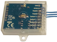
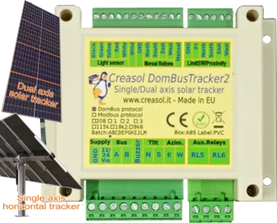
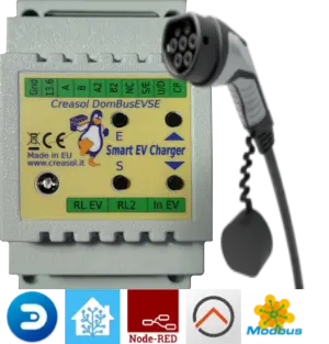
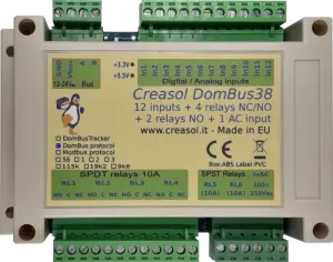
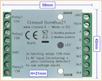
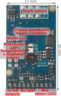
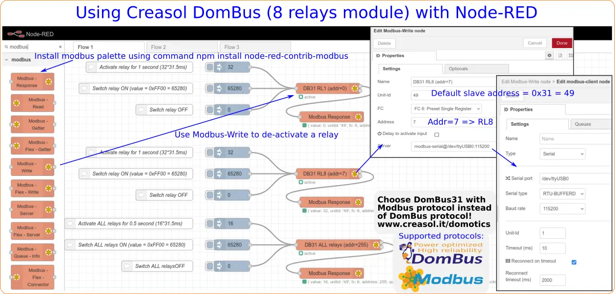
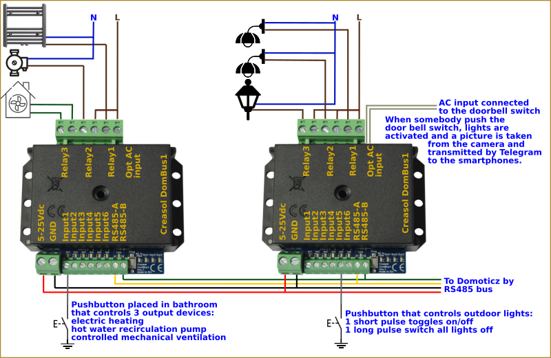
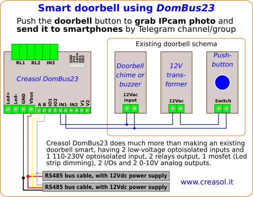
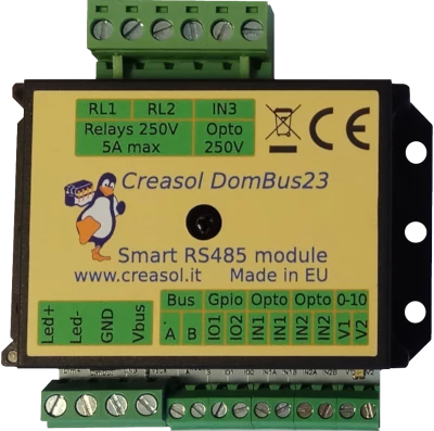
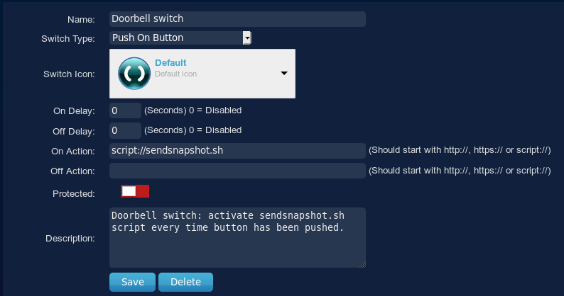

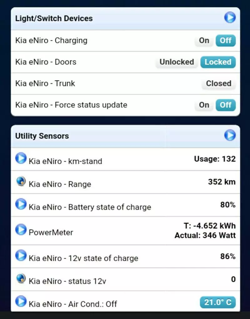 Einführung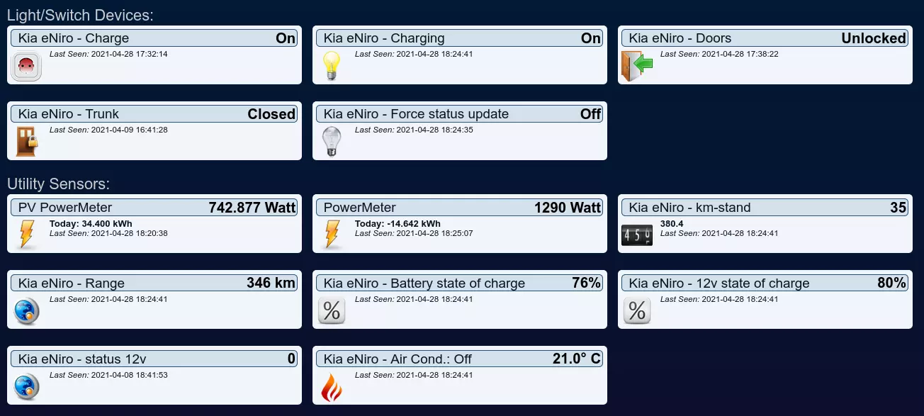

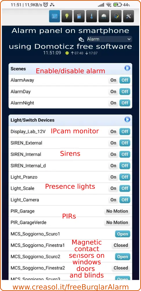 Das Ziel besteht darin , sich ein komplettes Alarmsystem aufzubauen, das zuverlässig, skalierbar, kostengünstig und funktionsreich ist .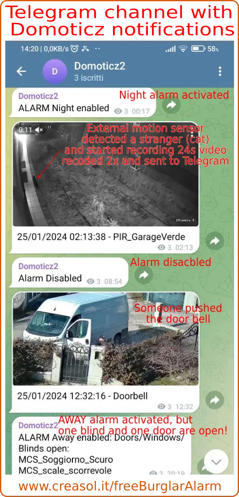
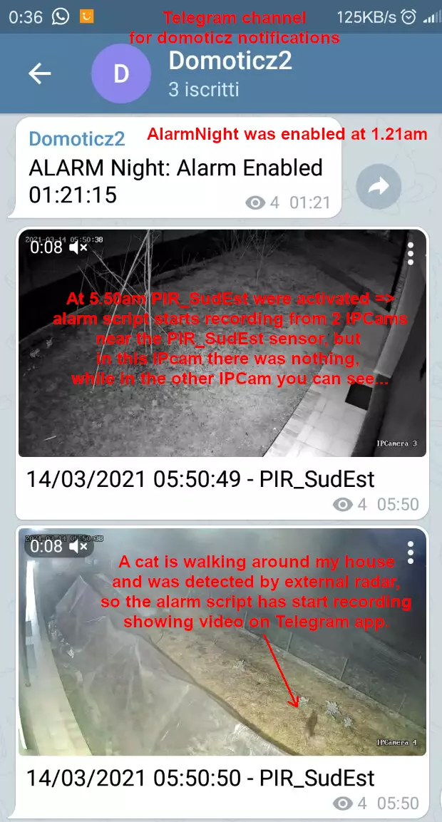
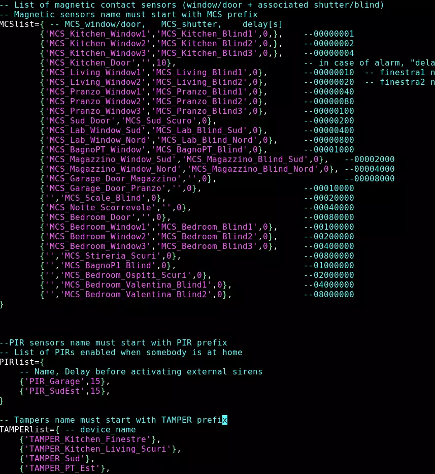
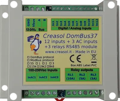
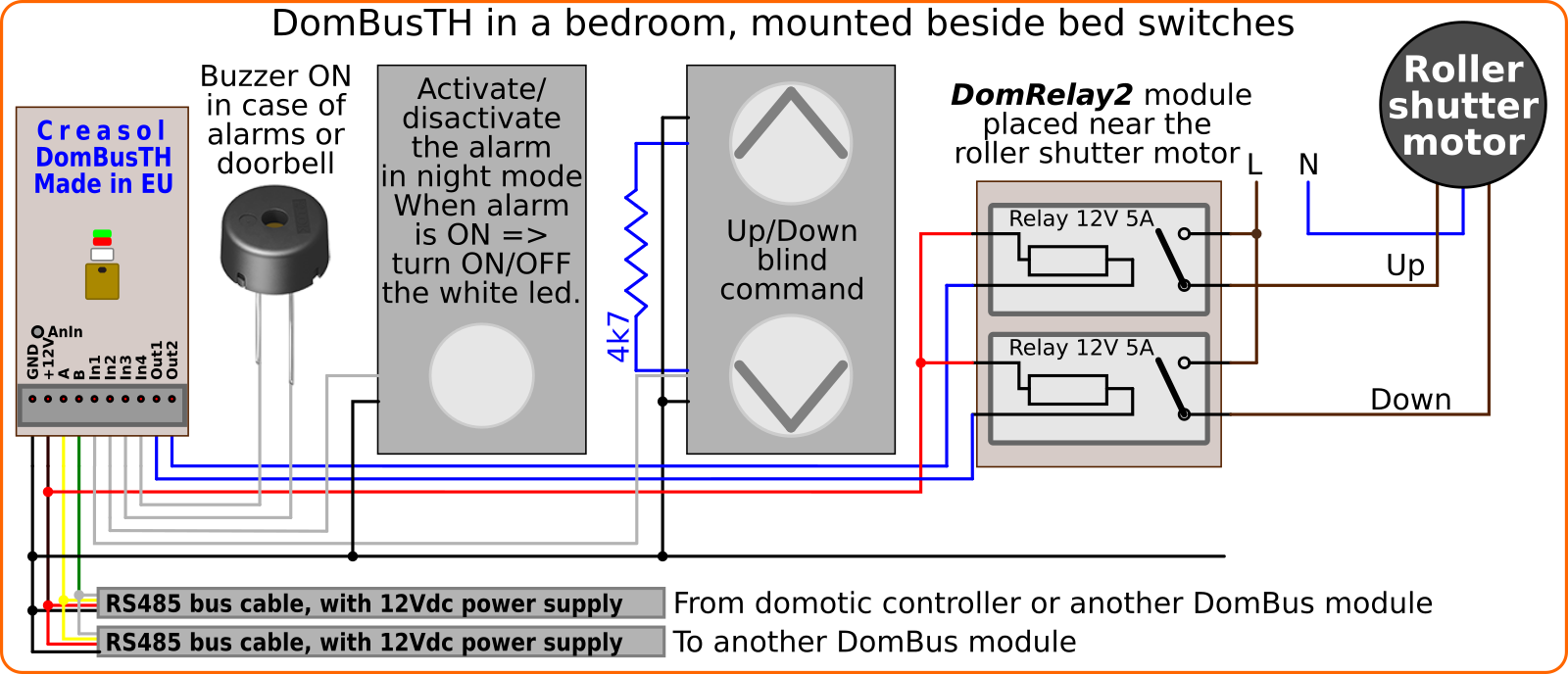
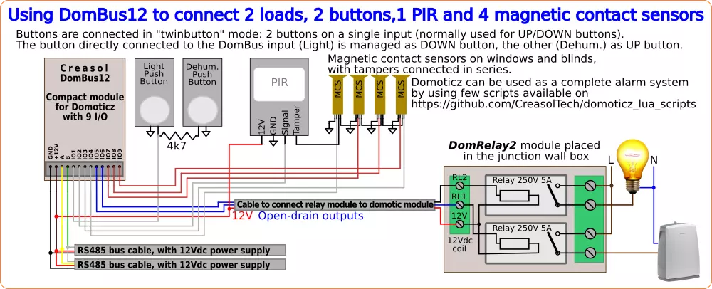
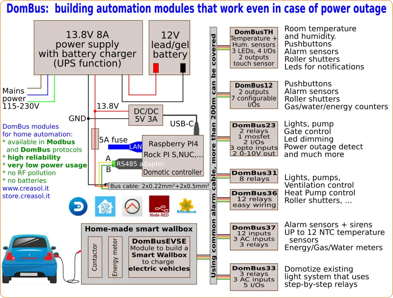
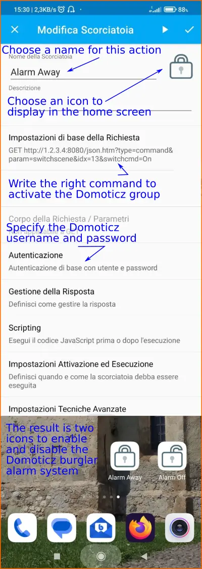 Domoticz unterstützt viele HTTP-Befehle zum Aktivieren von Szenen, Gruppen, Schaltern usw. und Smartphones verfügen über viele Anwendungen, mit denen solche URLs aufgerufen werden können.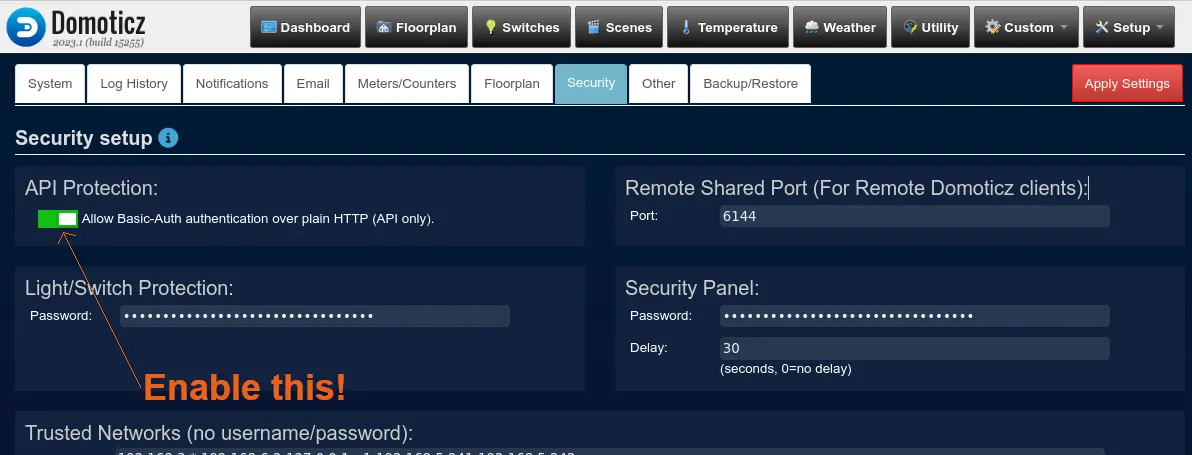
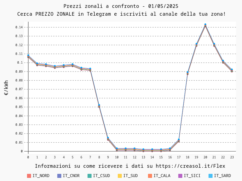
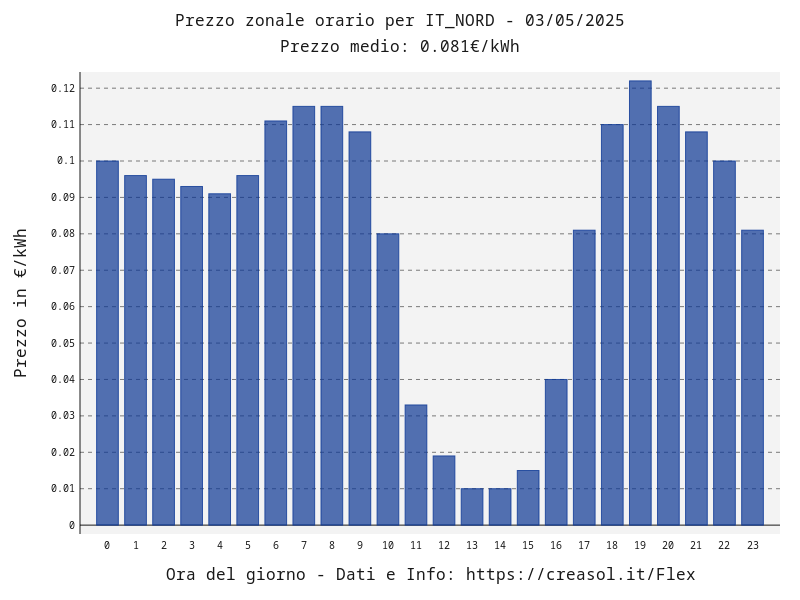
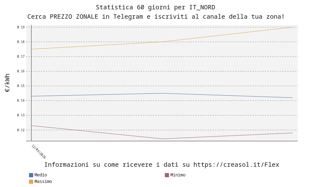
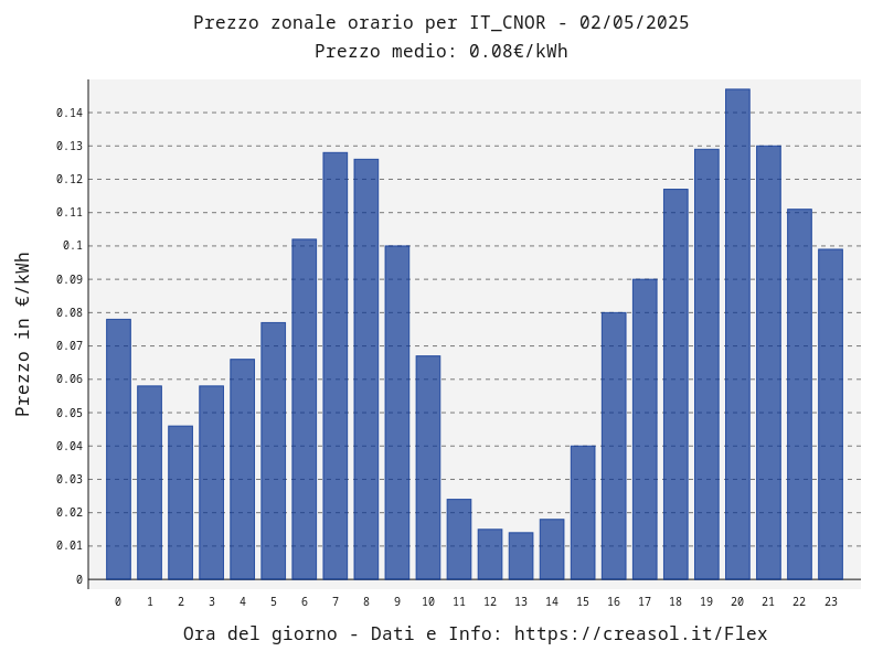
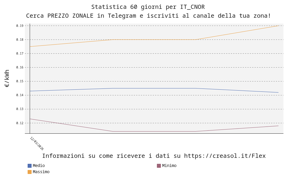
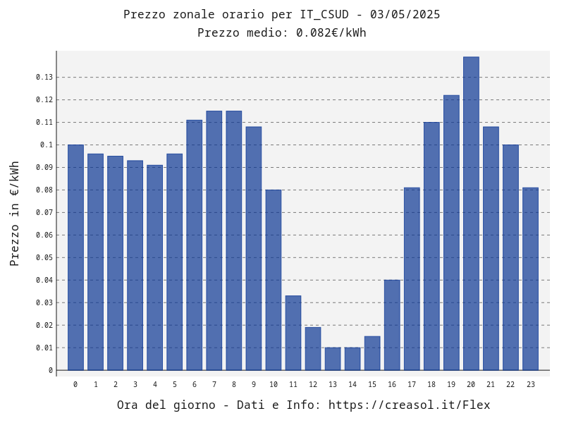
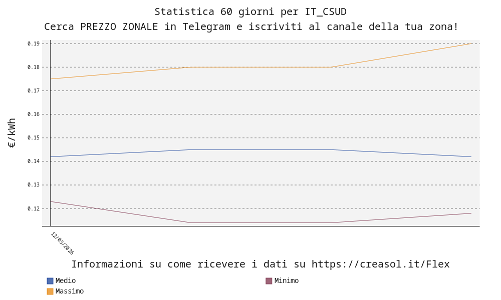
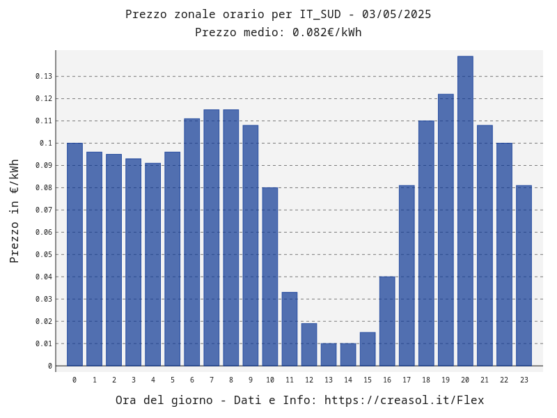
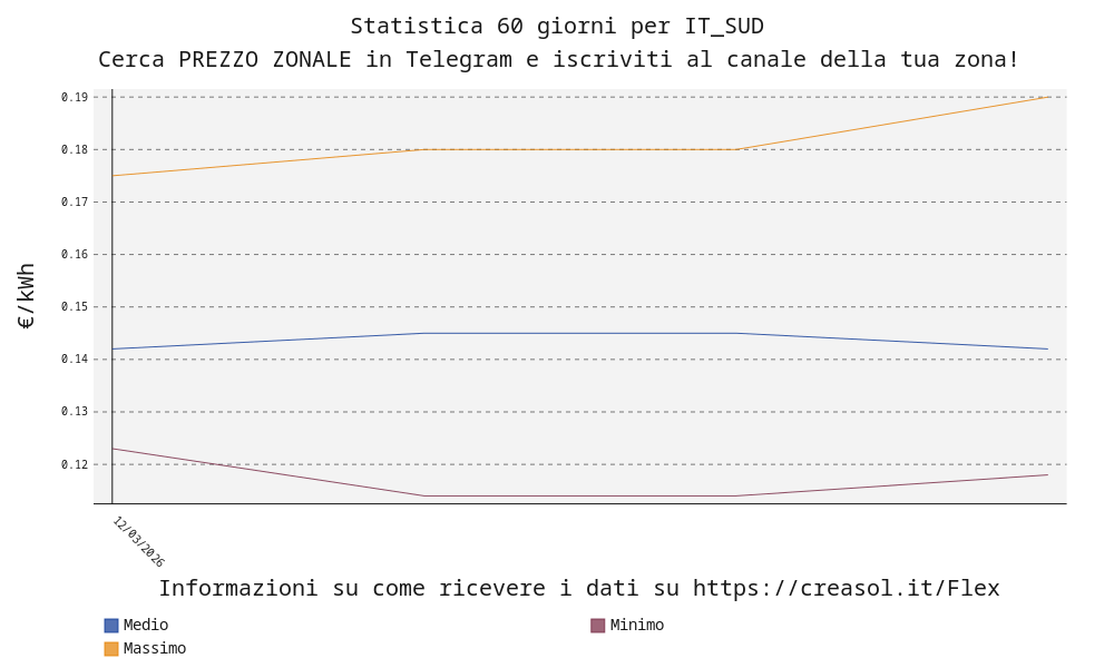
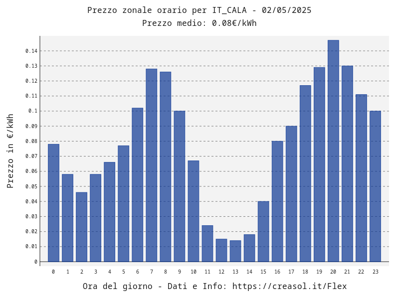
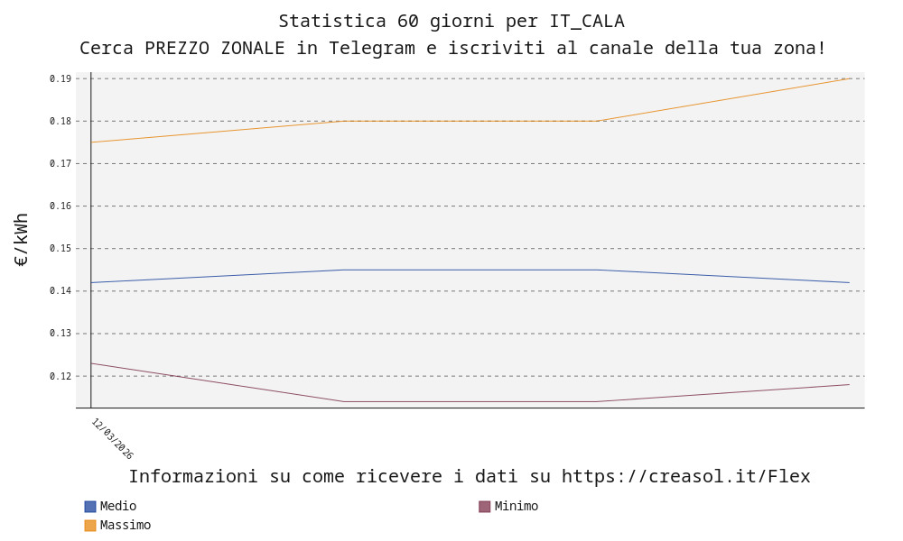
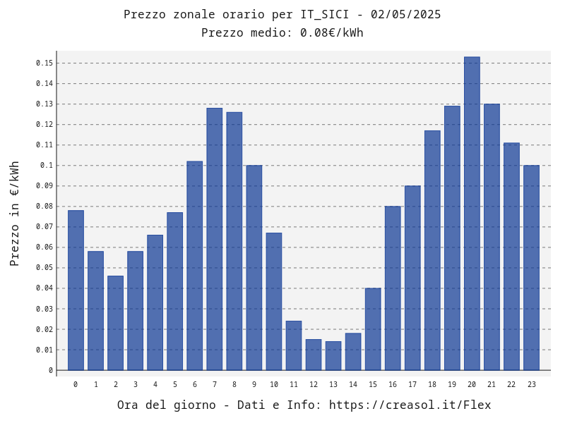
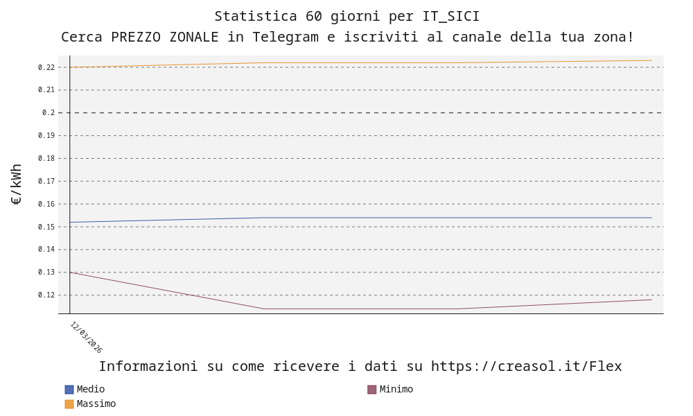
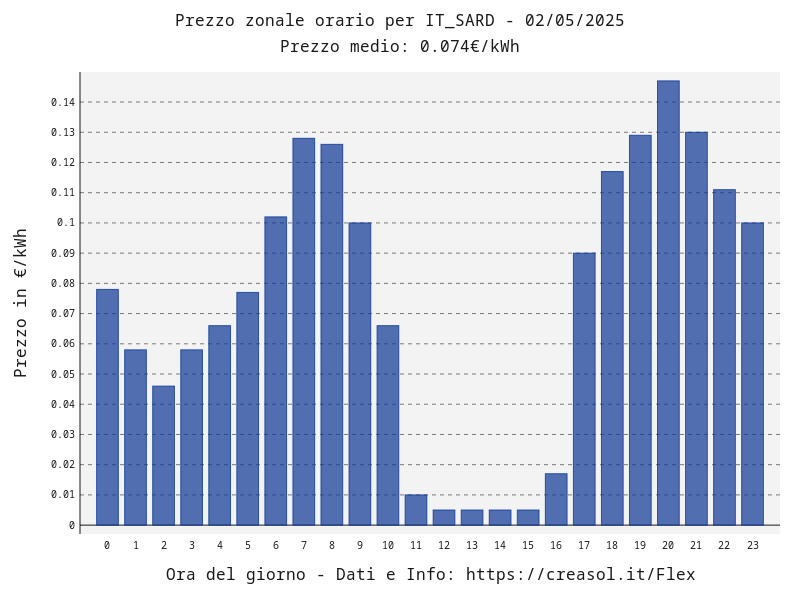
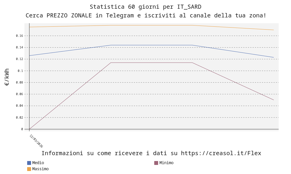
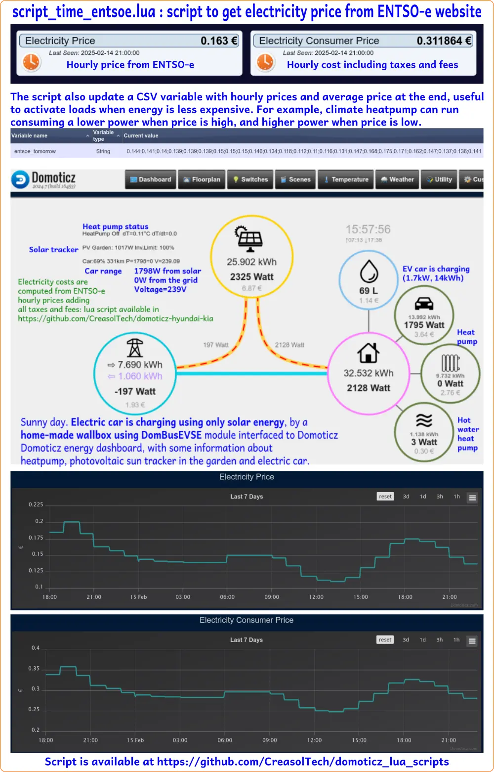
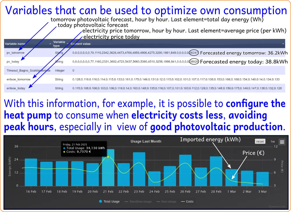
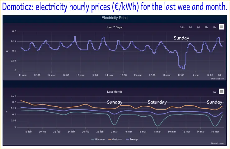
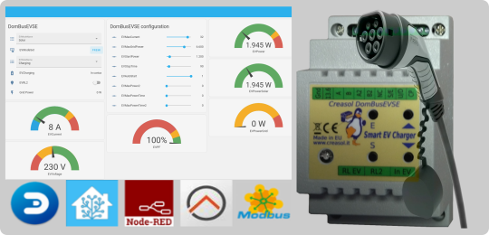 Jeder Nutzer eines Elektroautos möchte sein Auto intelligent laden :
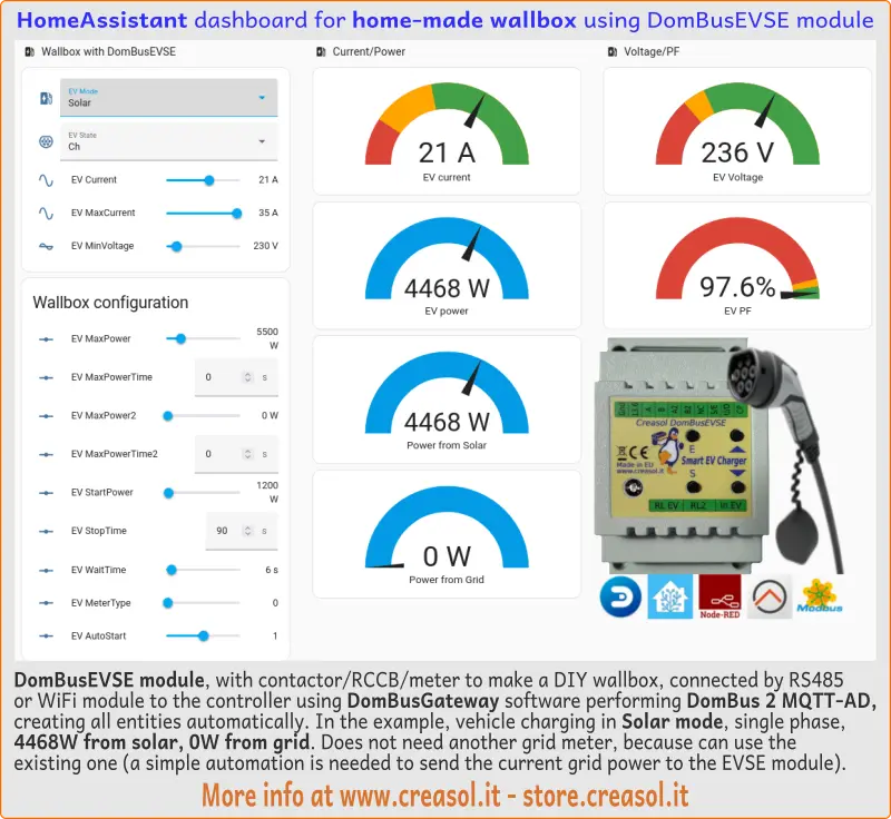
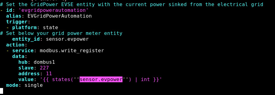
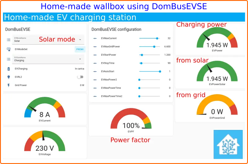
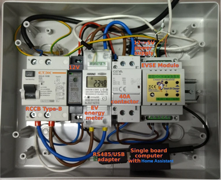
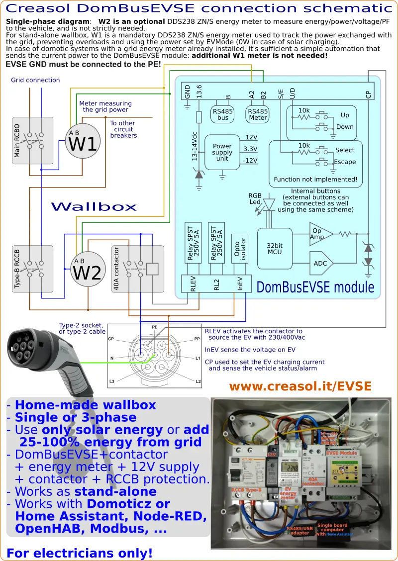
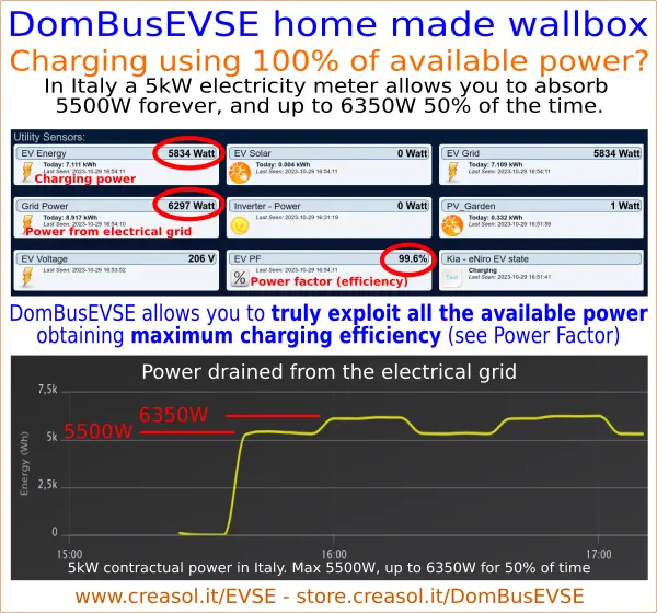
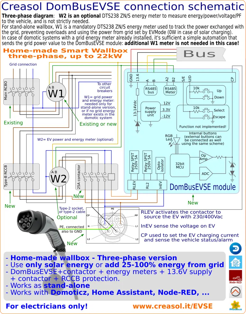
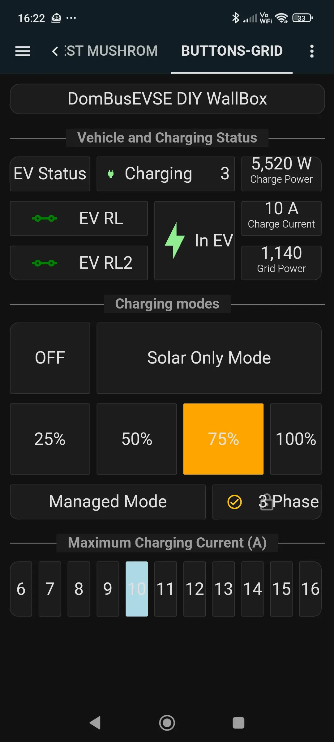
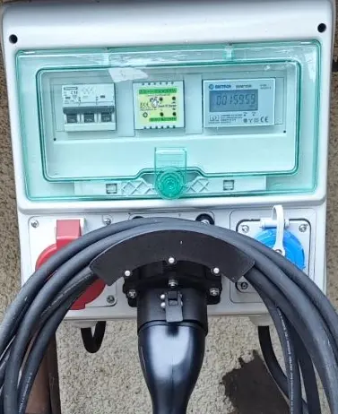
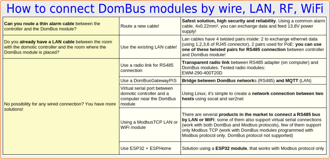
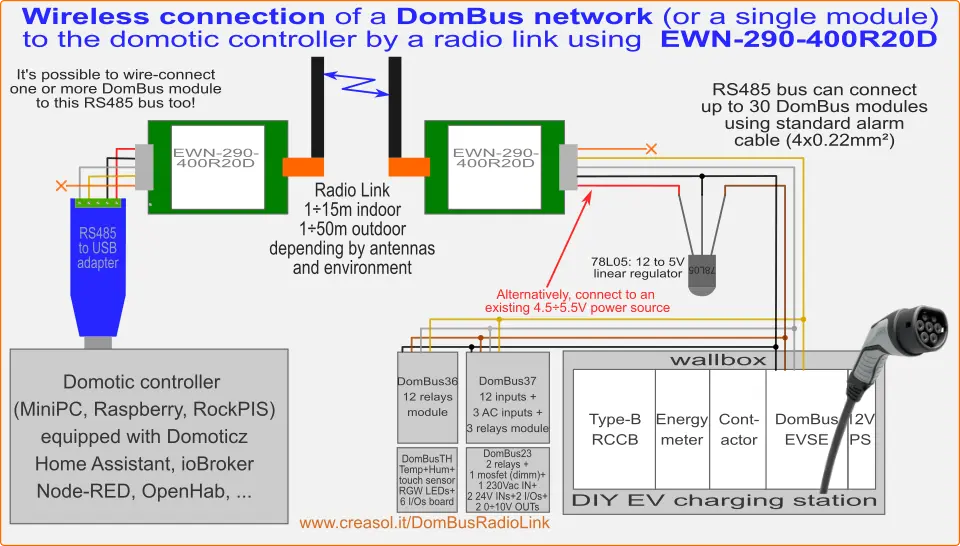
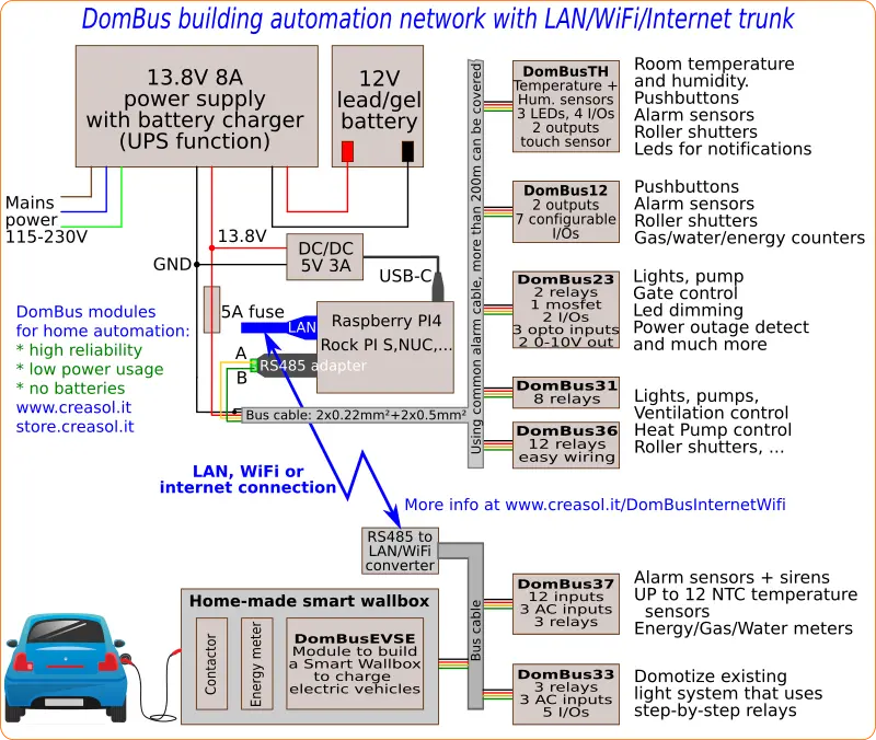
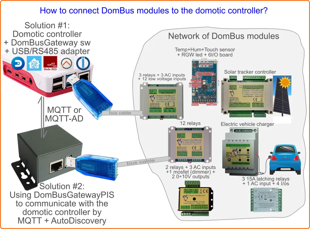
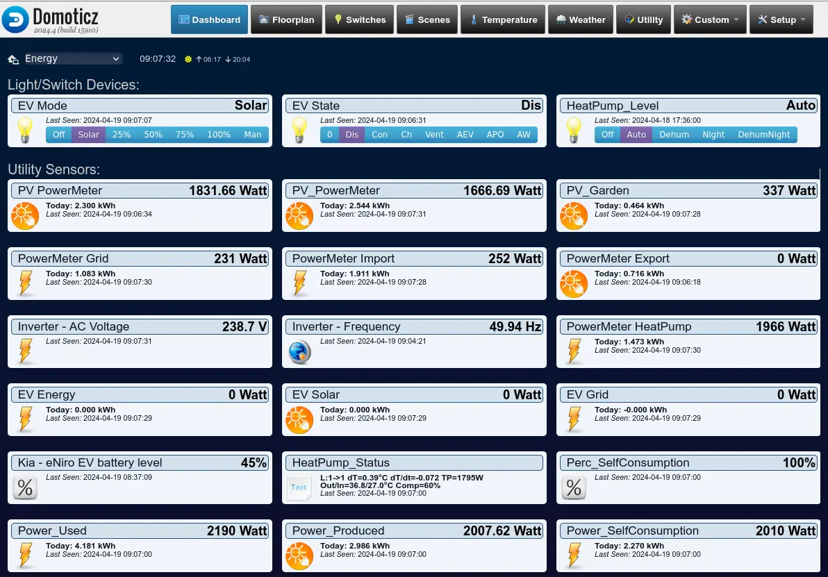
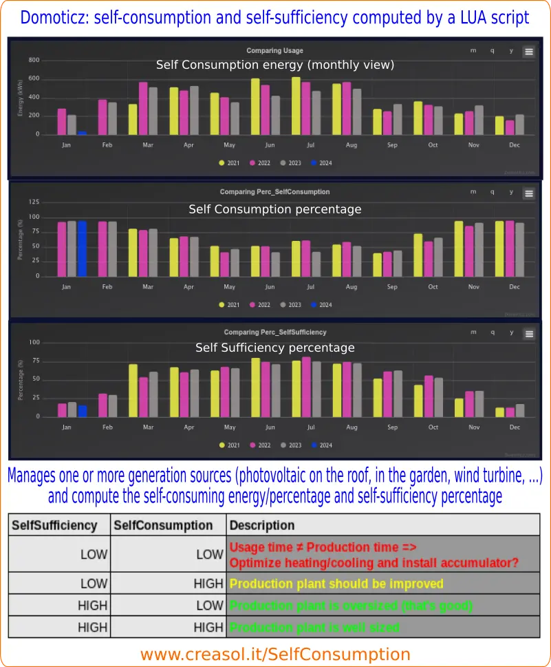
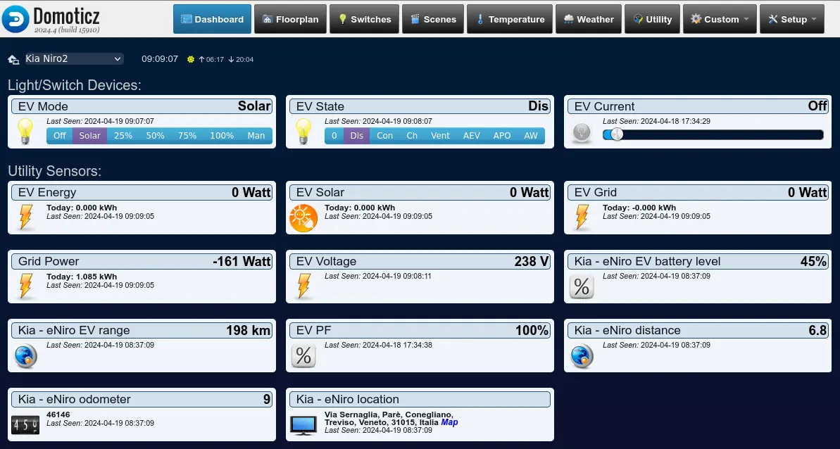
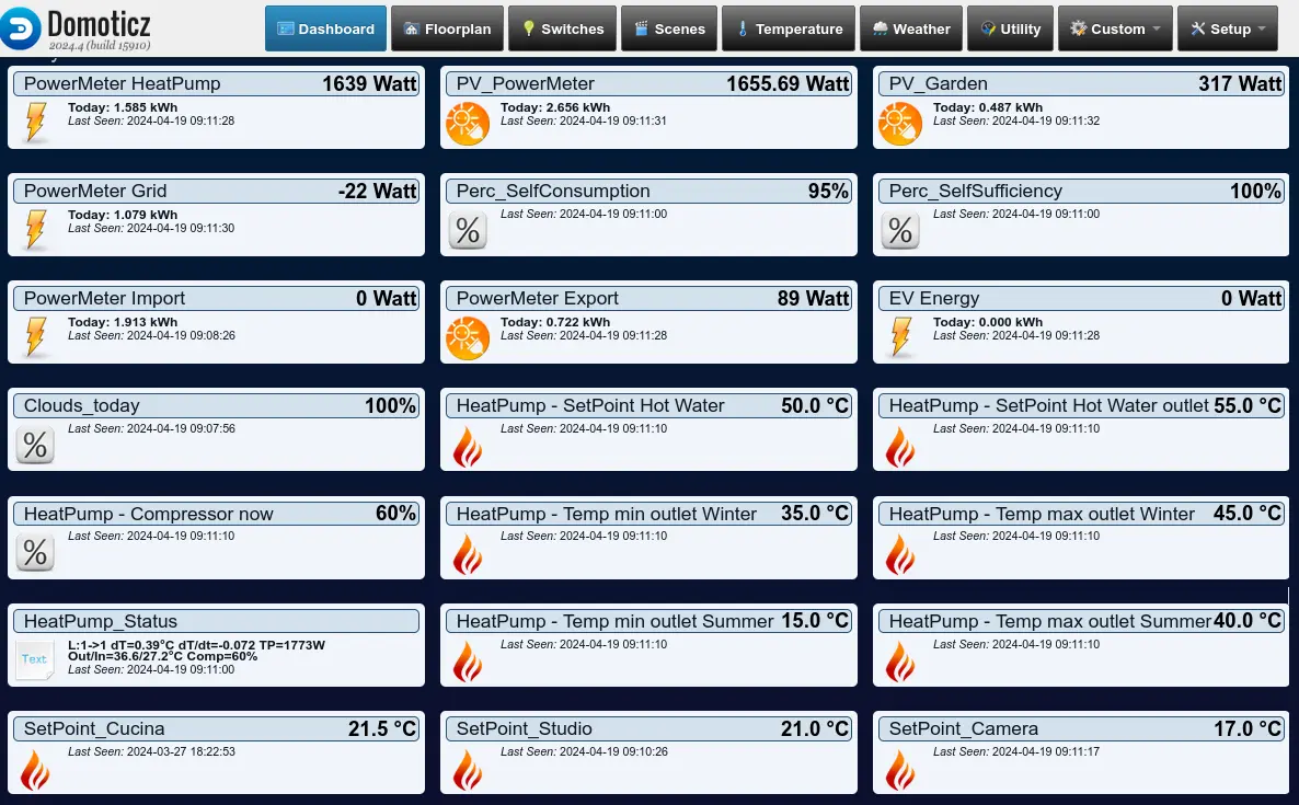
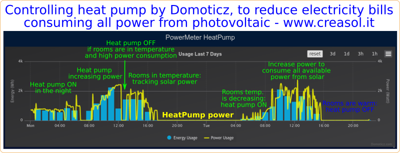
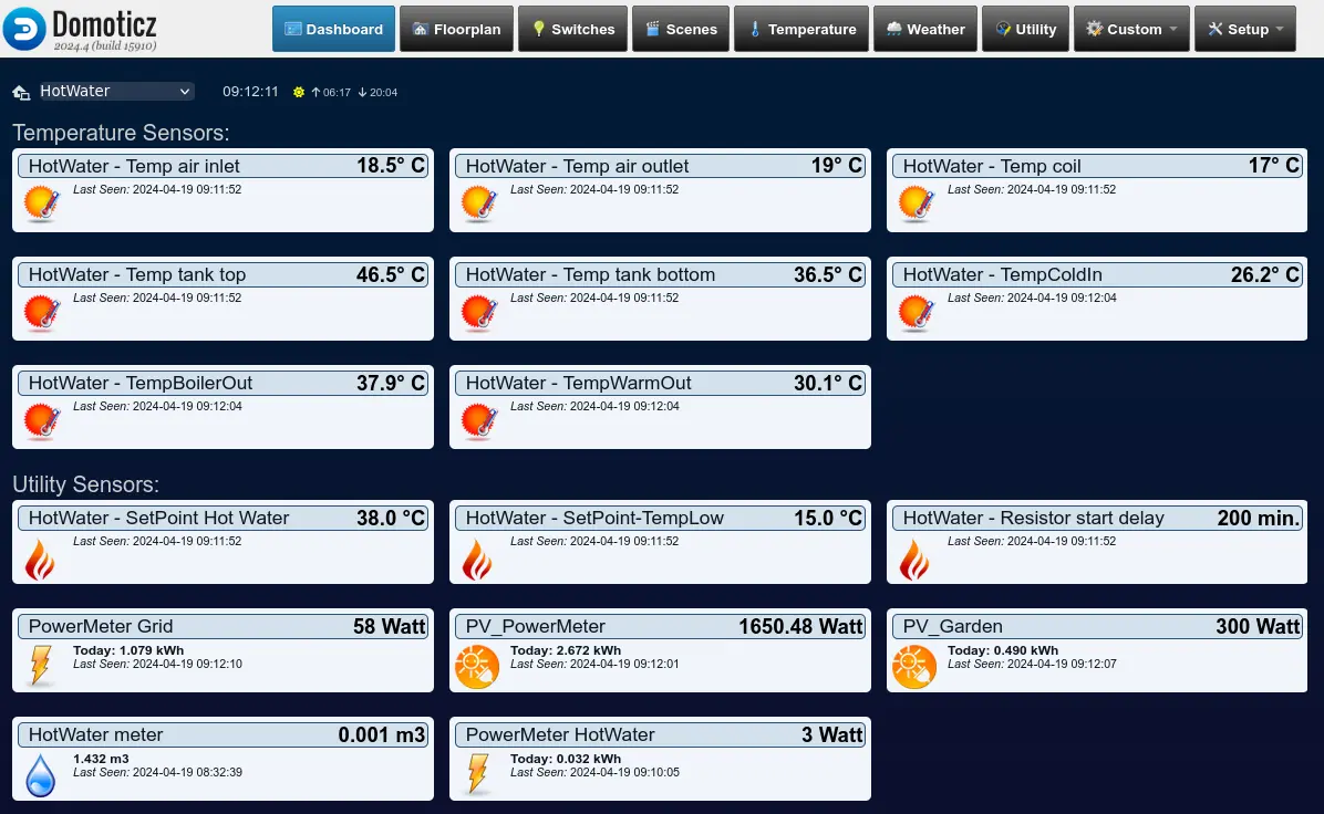
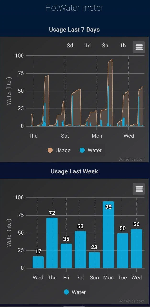
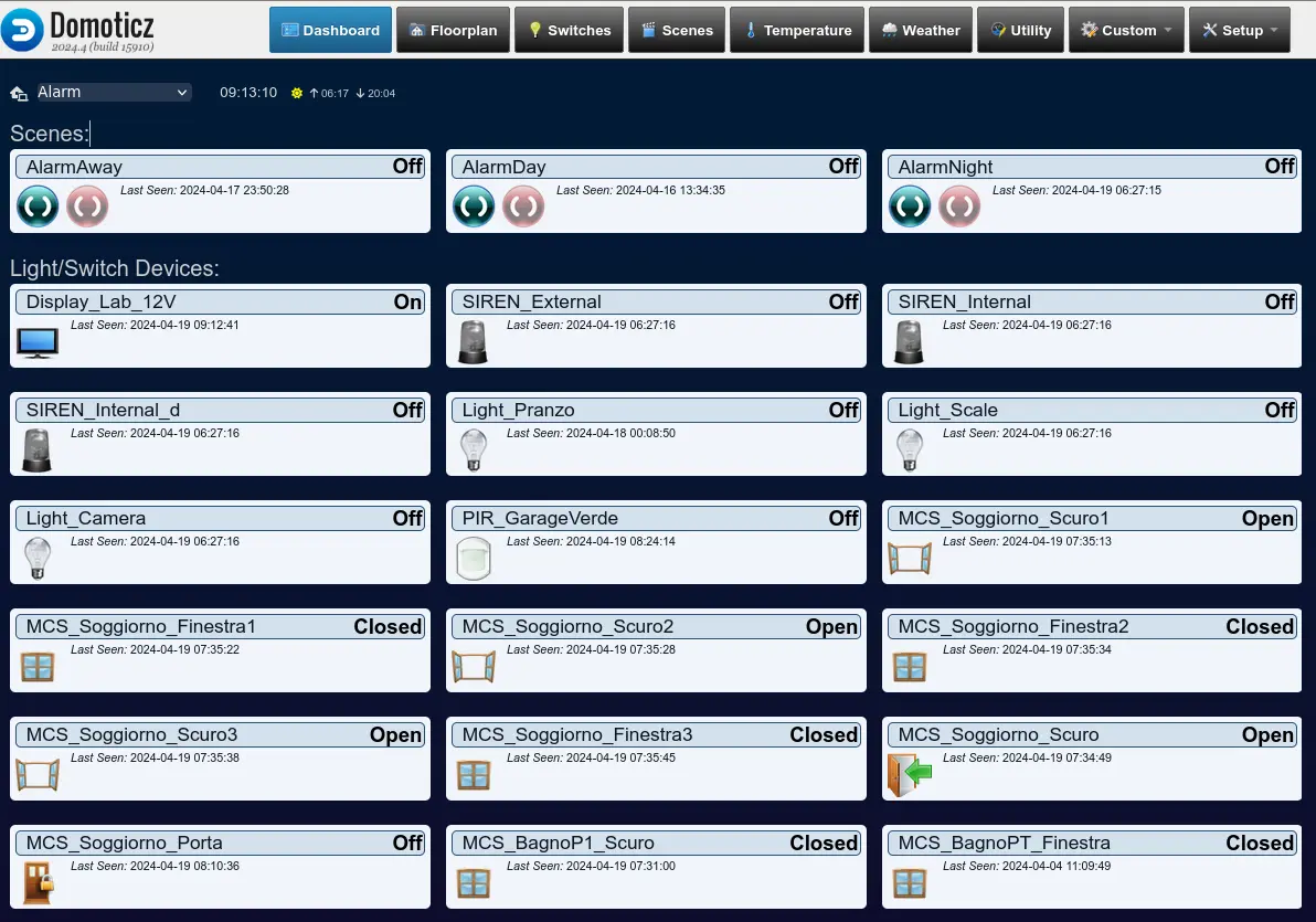

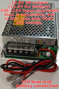 Choose a reliable power supply for the bus: we suggest to use a 13.5V power supply unit with lead-acid battery charge feature. Power supply should be strong enough to supply domotic bus, network switches and routers, IPCams and NVR, ... , so the whole system can work even in case of power outage.
 Choose a low power domotic controller: for small system you can use
  Choose a reliable power supply for the domotic controller, if used: the best solution is a a DC/DC converter with Type-C or MicroUSB connector, supplied by the 13.5V power source, so the domotic controller is protected from blackout.
 Connect the domotic bus data to a RS485/USB adapter, and supply wires to the 13.5V power supply through a fuse. Use RS485 cables or, alternatively, common alarm shielded cables: 2x0.22mm² for data and 2x0.5mm² for Vbus supply. Connect the shield to GND only on one side.
 In any room where you have to measure temperature and humidity, place a
 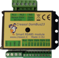 If you need to interface a gate or garage door, you can use
  If you need several inputs for alarm sensors (magnetic contact sensors and PIRs), you can use the compact
 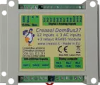 If you want to make a homemade alarm system and need more inputs and also some outputs, you can use
 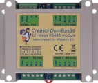 If you need more relays, we have
  Use
Use  Use
Use 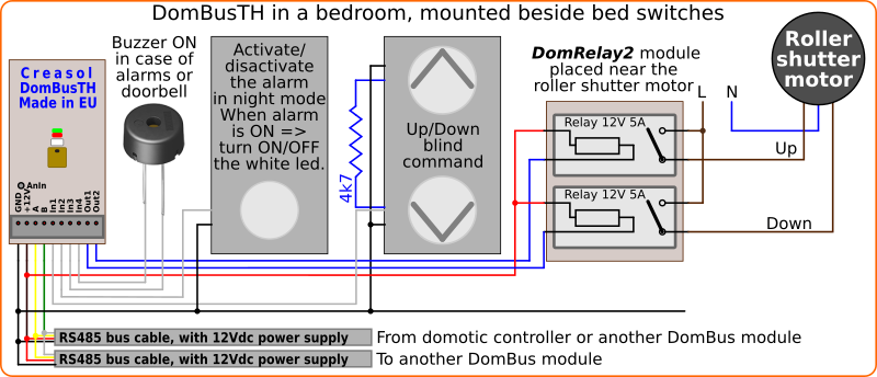
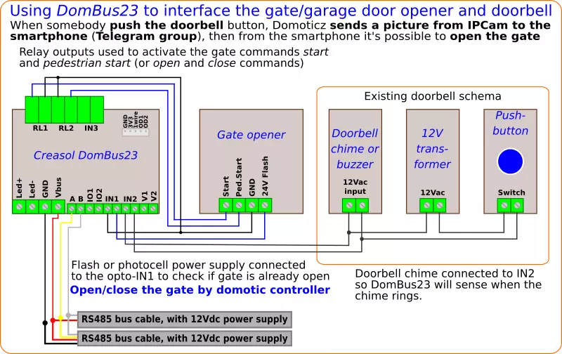
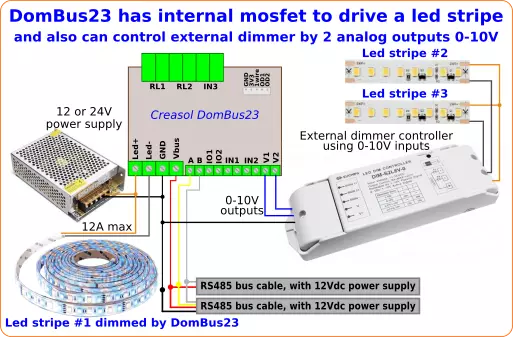
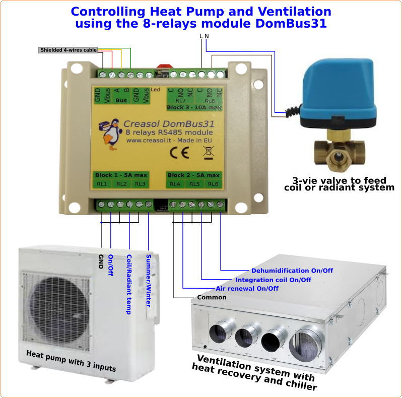
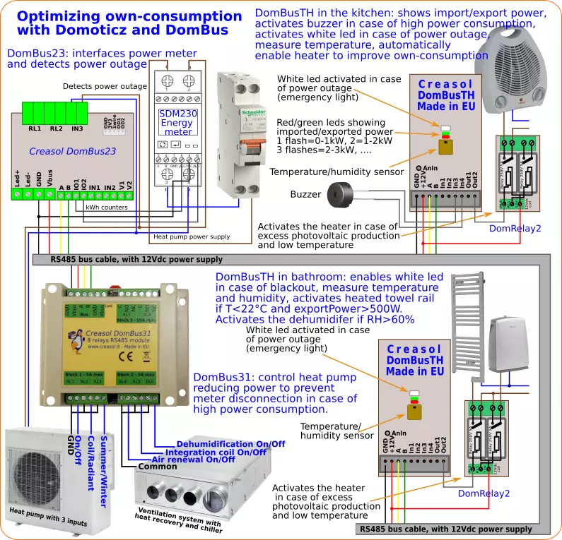
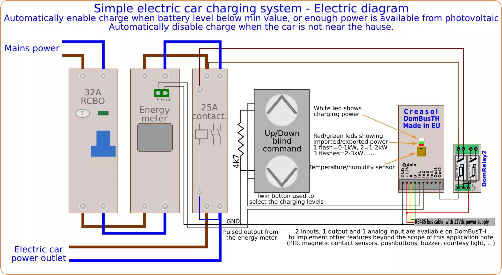
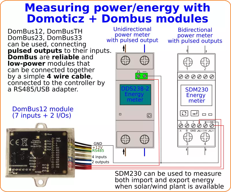
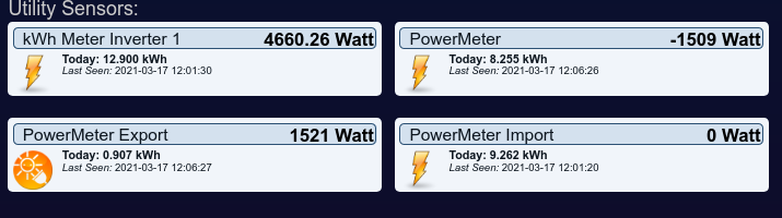
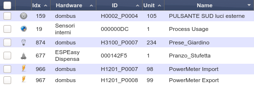
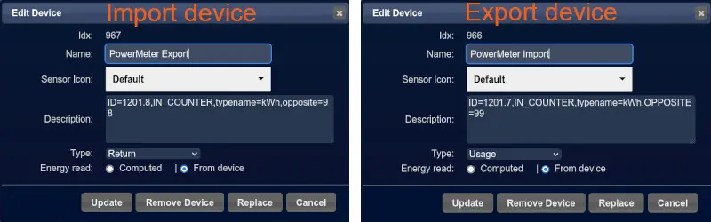

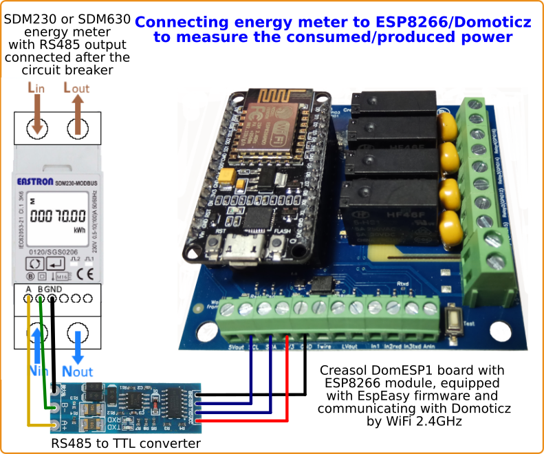
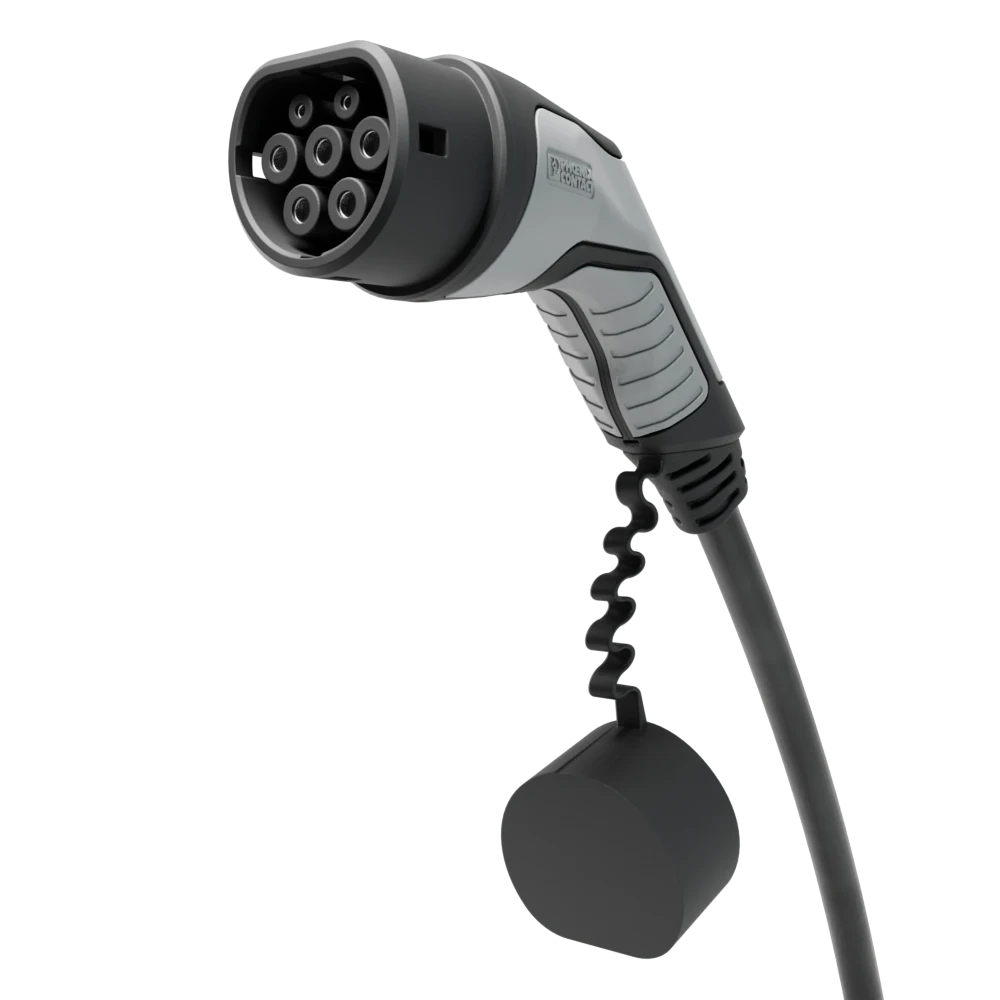
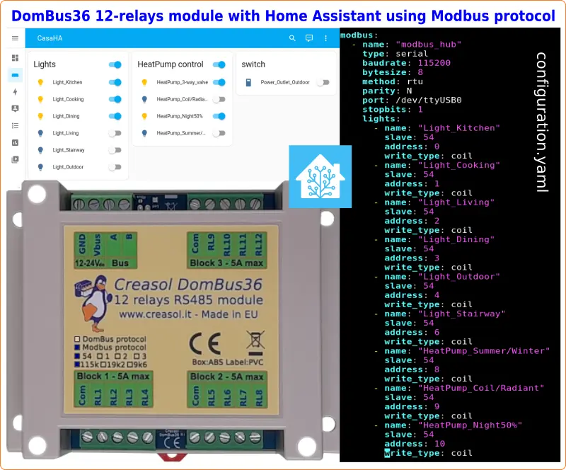
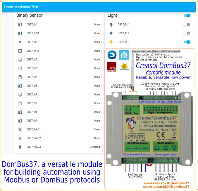
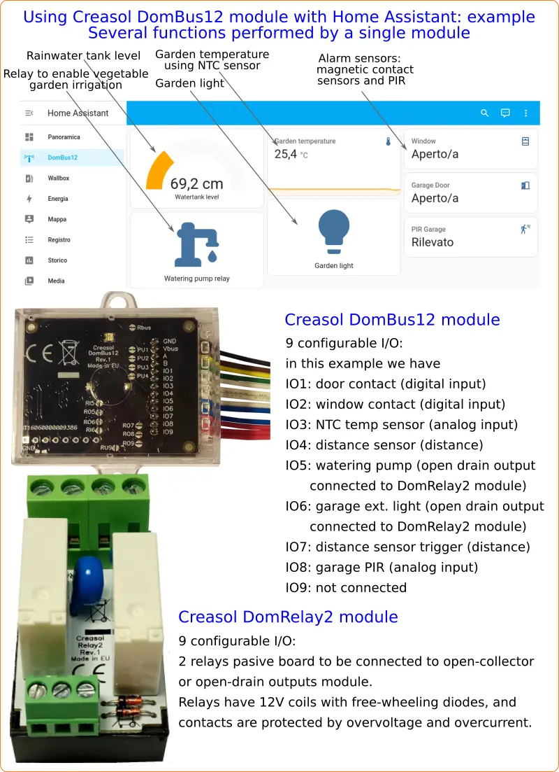
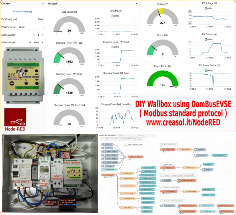
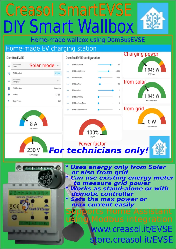
 Wasserdurchflusssensoren sind nützlich, um den Kalt- und Warmwasserverbrauch zu messen. Einige Wasserdurchflusssensoren basieren auf einem Hall-Sensor zur Messung der internen Rotordrehung und erzeugen Impulse von bis zu 100–200 Hz.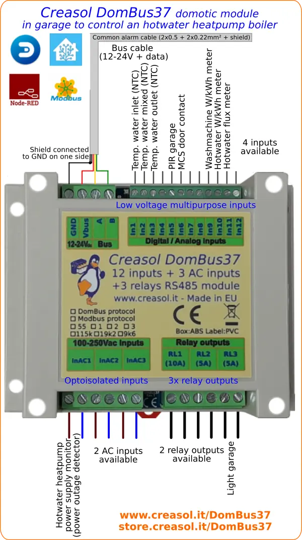
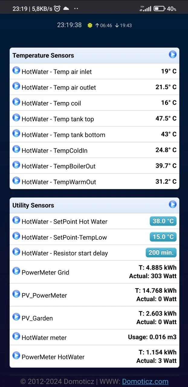
 The following application note shows how to measure the level of rainwater (or other liquid) inside a tank, using a waterproof ultrasonic distance sensor JSN-SR04T.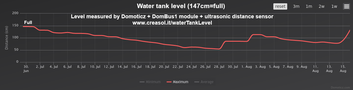
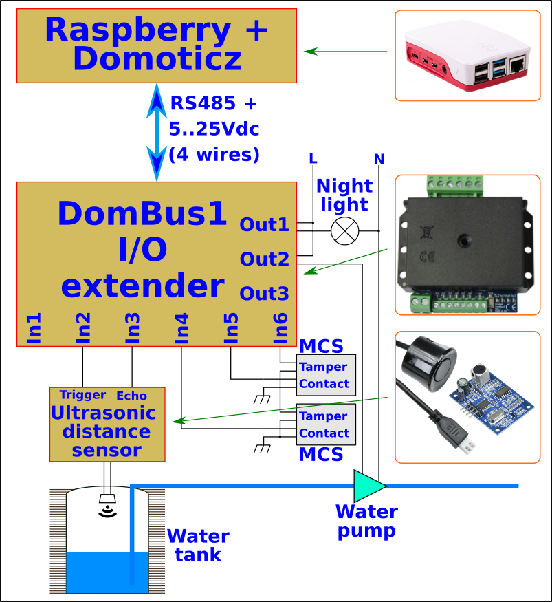
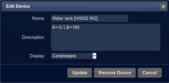
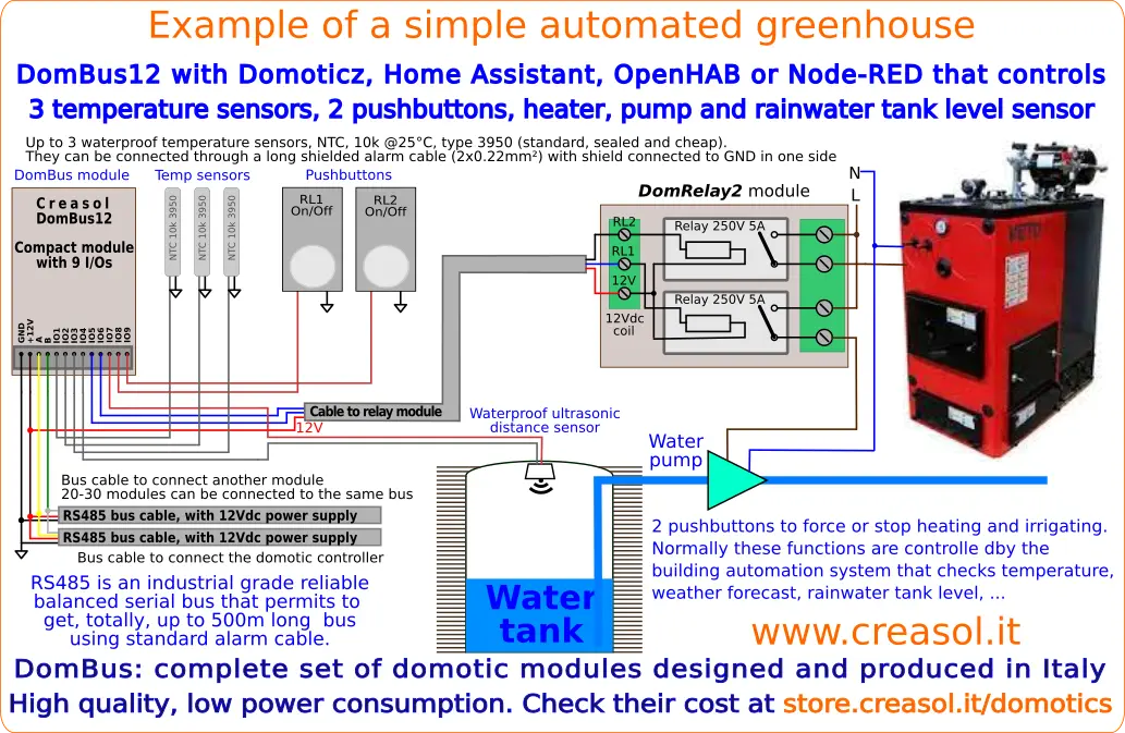
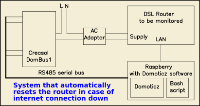
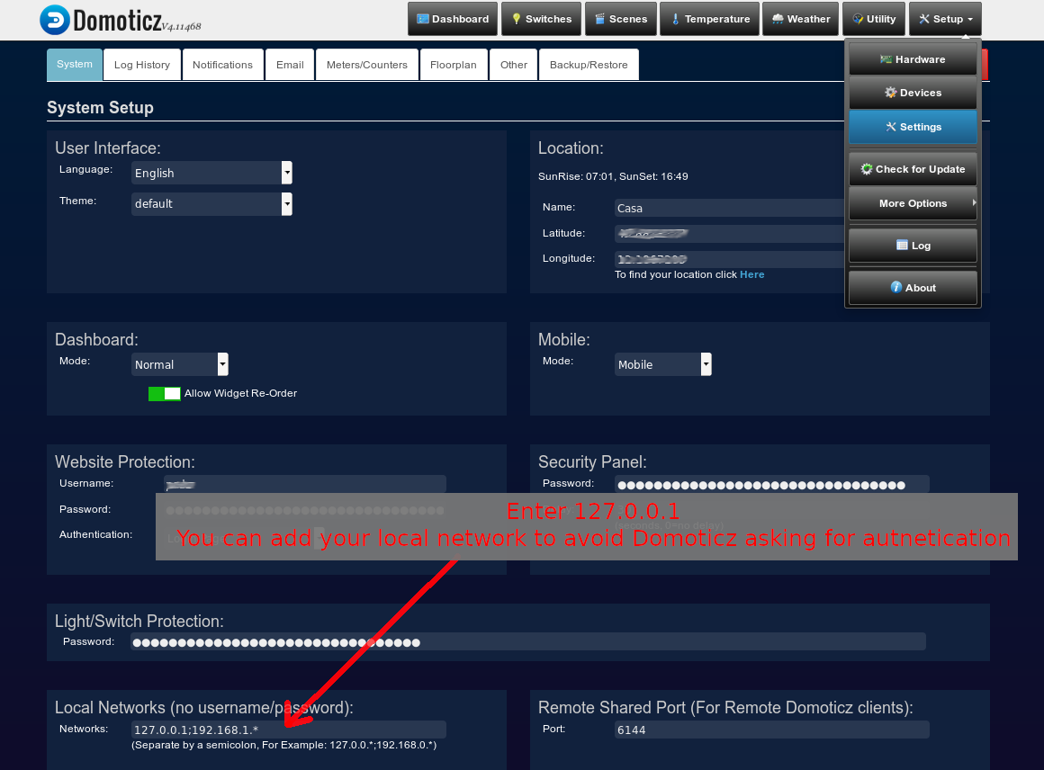
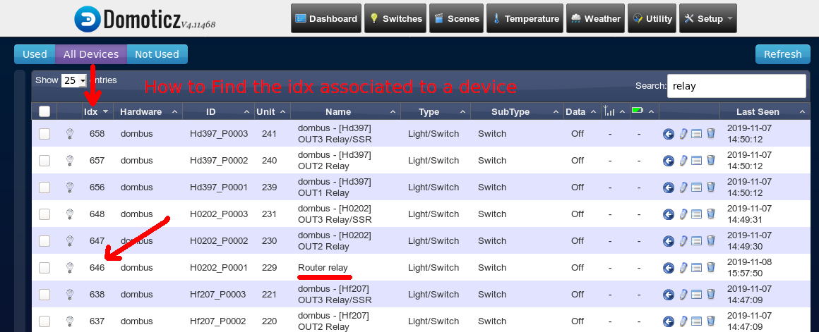

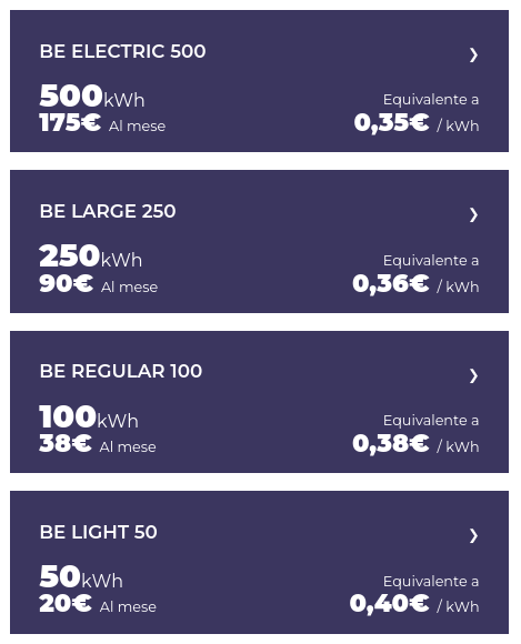 ono colonnine veloci (150kW o più di potenza) il cui costo a consumo è veramente alto, 0.89€/kWh, ma bisogna essere anche un po' furbi: ci sono le tariffe flat!
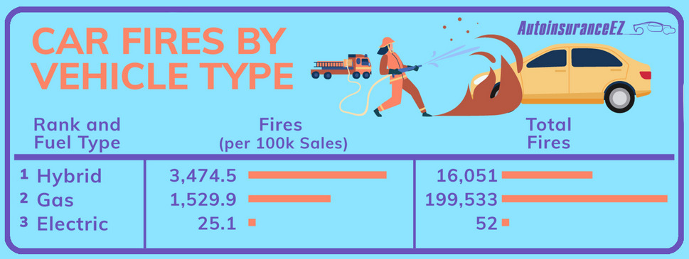
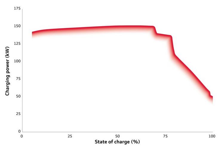
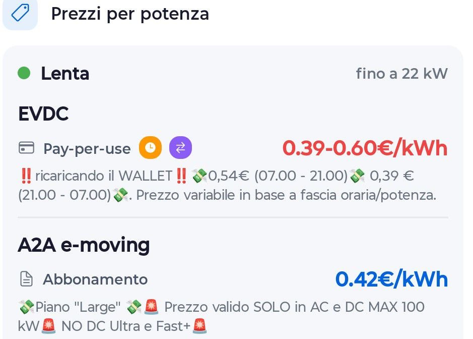
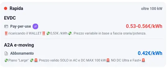
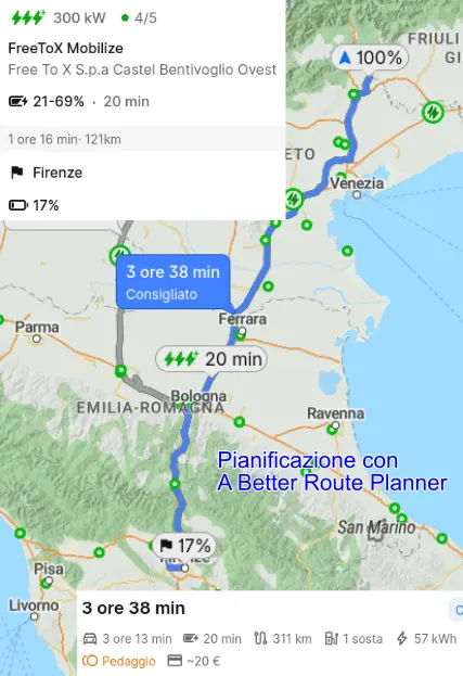
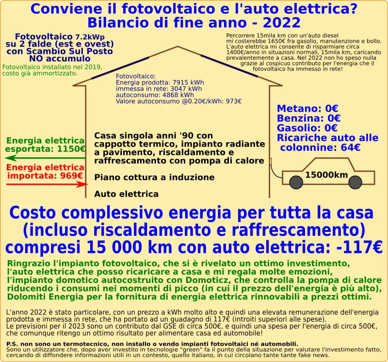
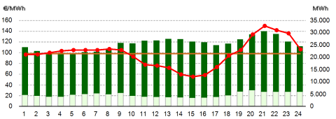
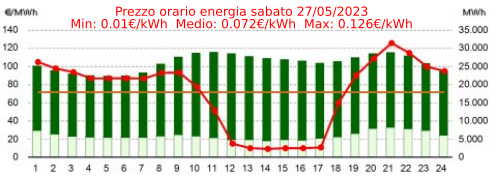
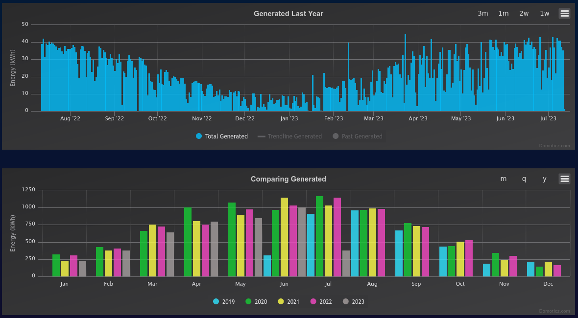
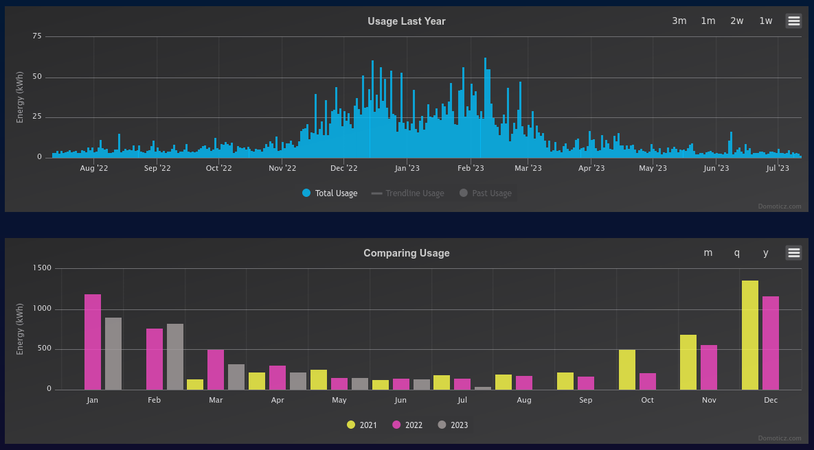
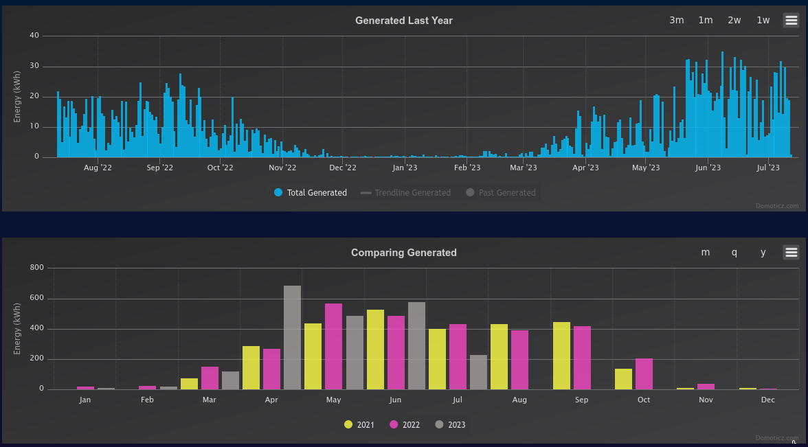
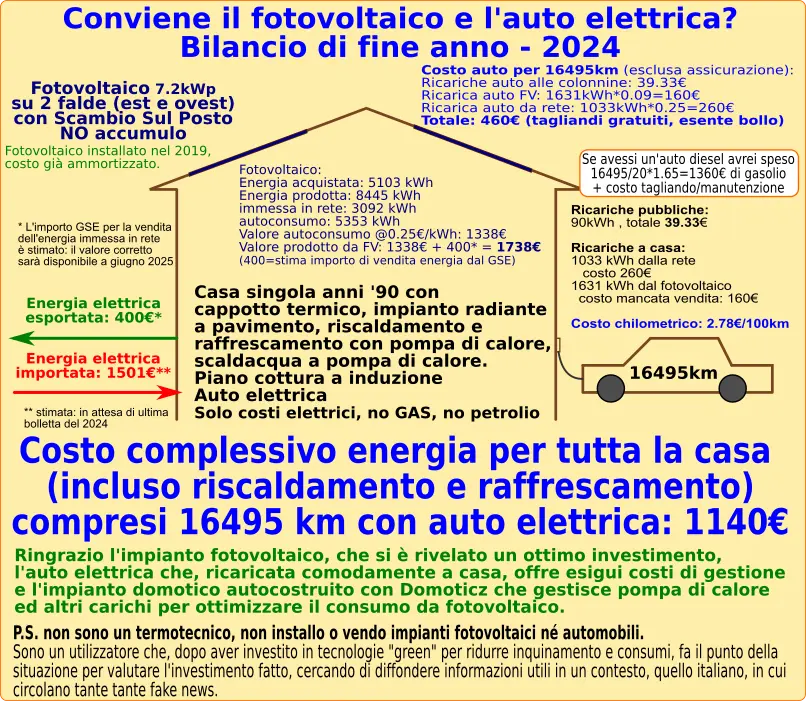
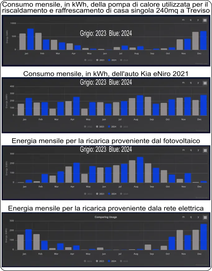
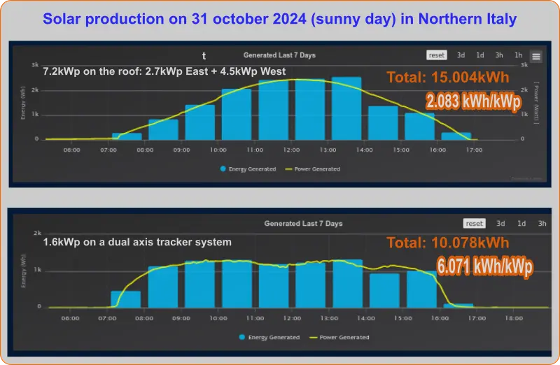
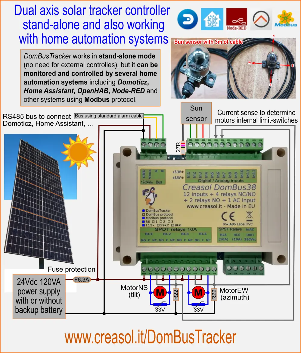
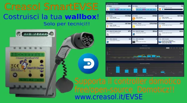
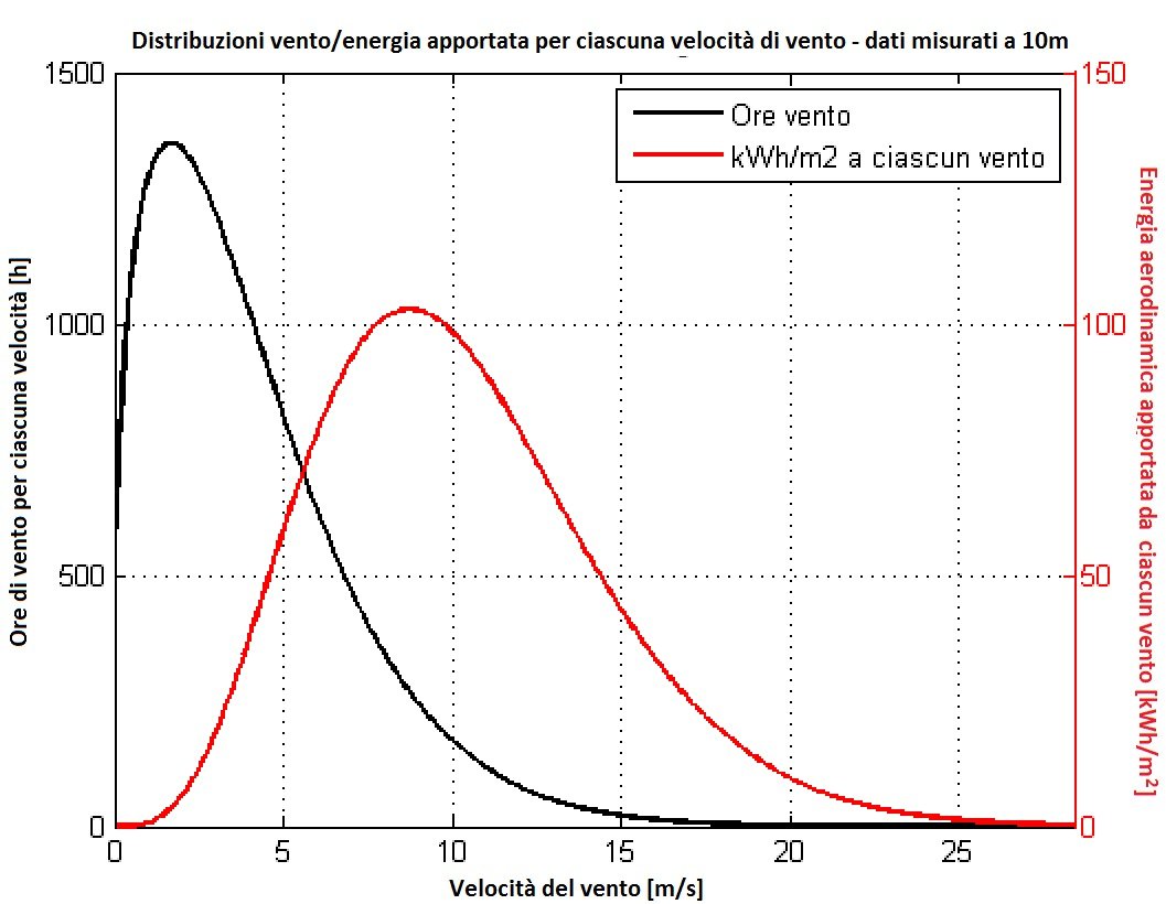
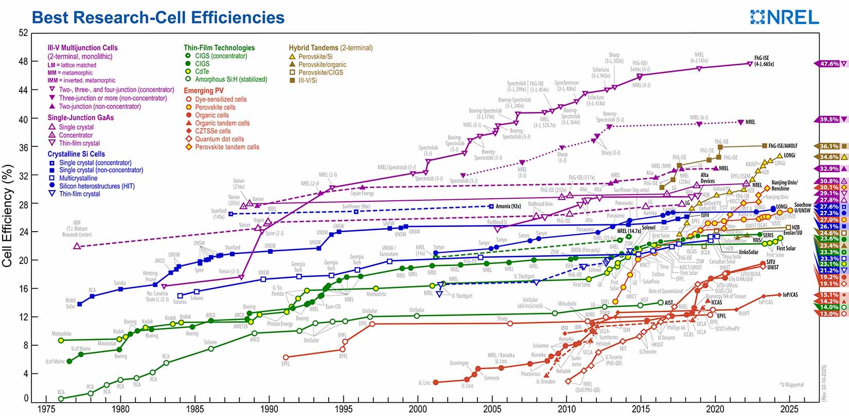

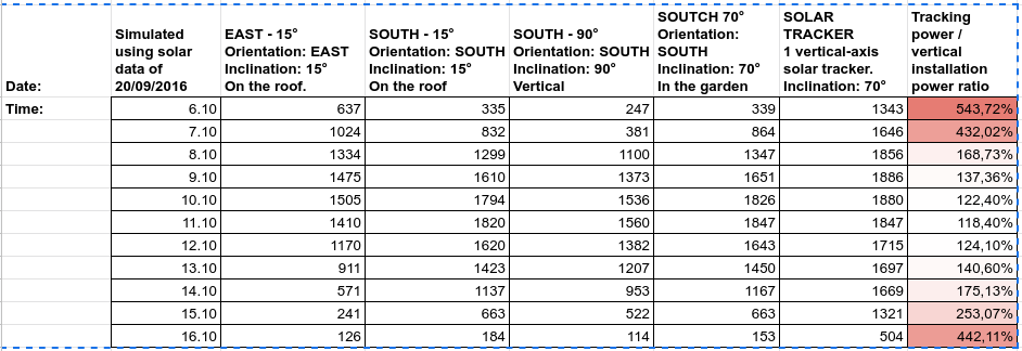
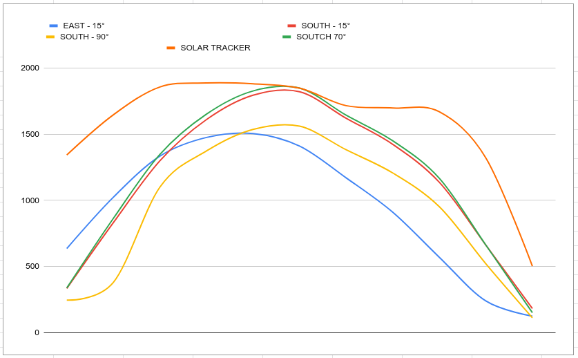
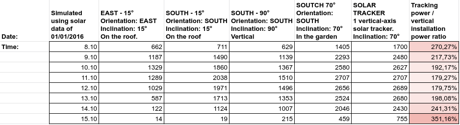
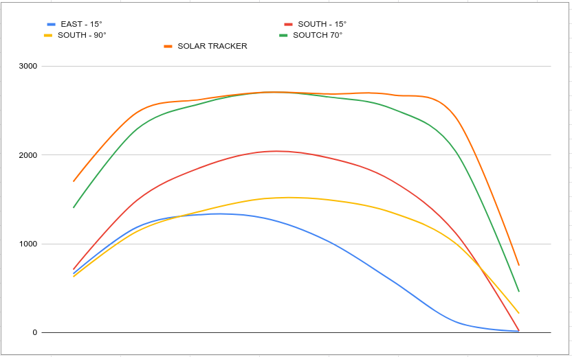
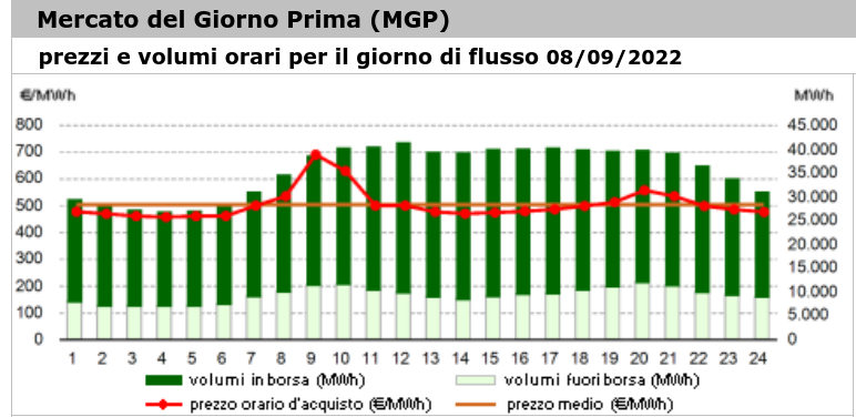
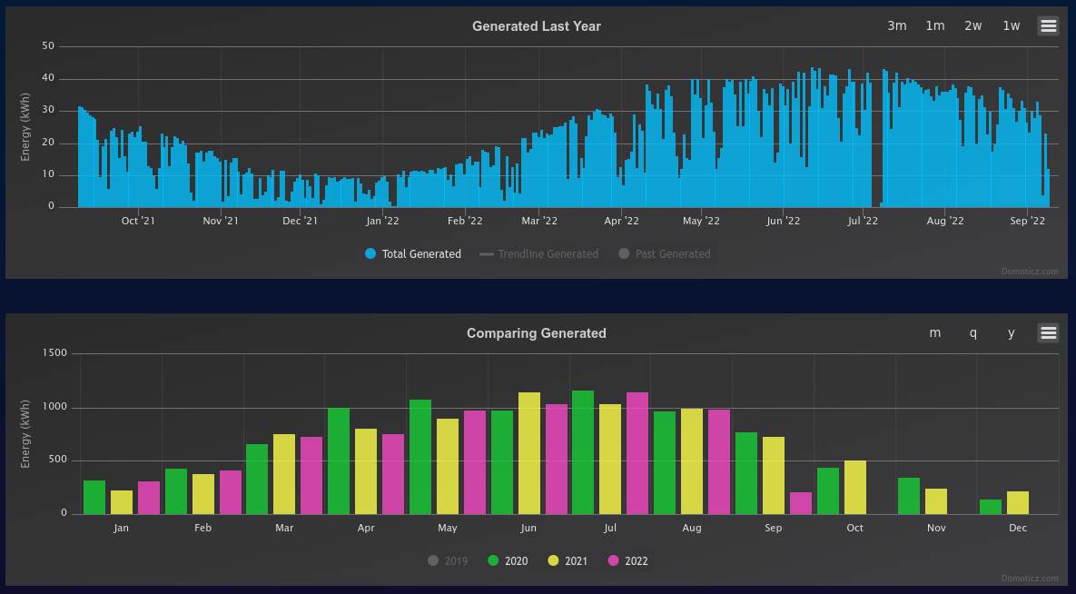

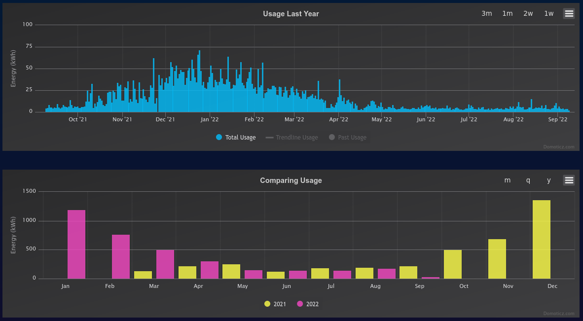
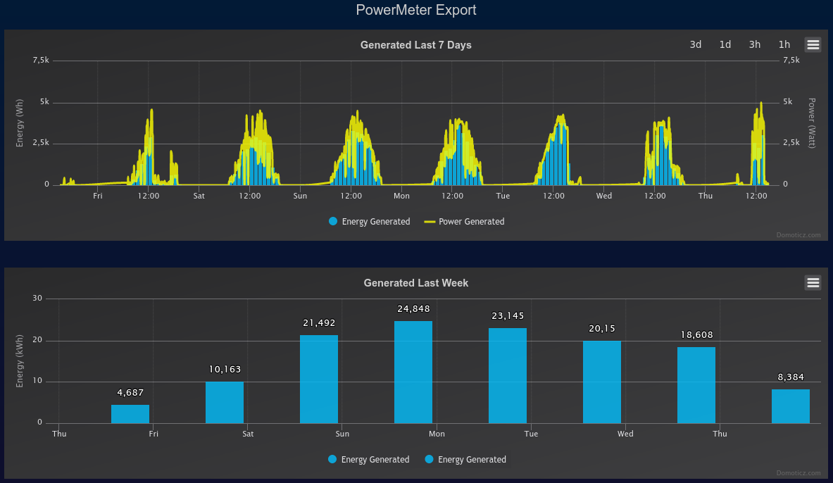
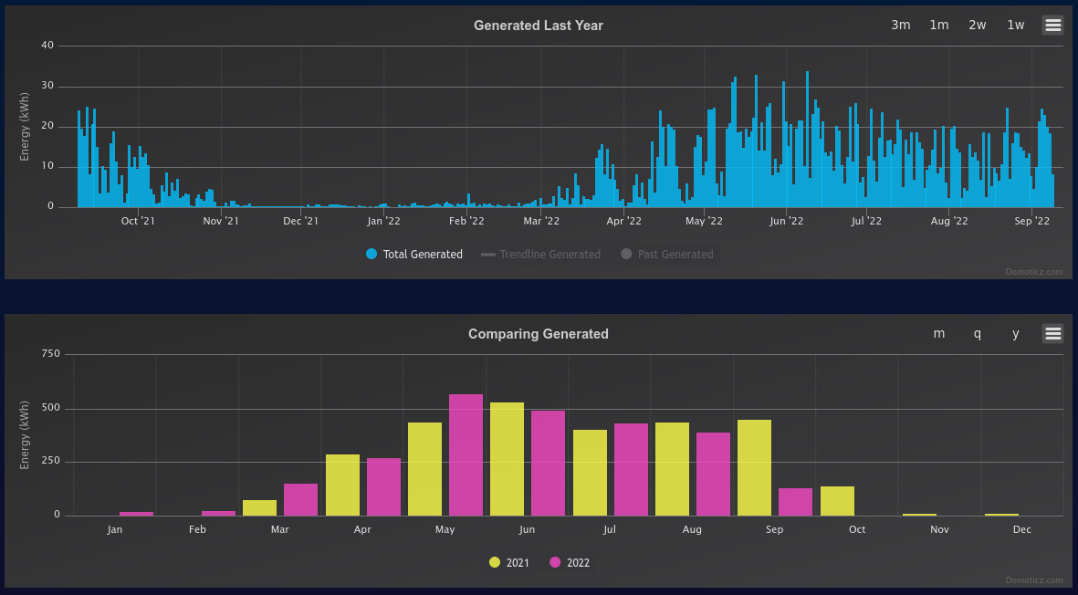
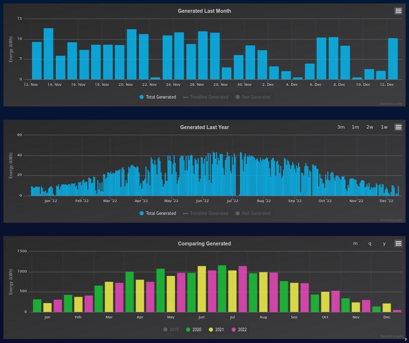
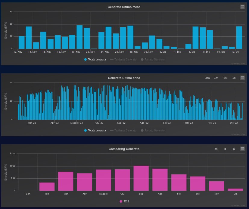
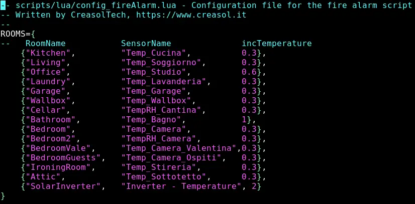

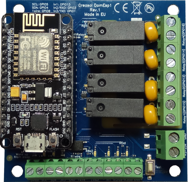 NodeMCU v3 is a very useful and powerful controller based on ESP8266 microcontroller with 2.4GHz WiFi, GPIO ports, analog input, I2C bus, UART and 1wire ports, equipped with a dual-in-line strip male connector.