Modulo domotico utilizzabile come inseguitore solare autonomo, mono o biassiale , funzionante in modo autonomo.
Può essere controllato anche da un sistema domotico , come Domoticz (versione DomBusTracker con firmware protocollo DomBus), Home Assistant, Node-RED, OpenHAB , ... (versione DomBusTracker con firmware protocollo Modbus).
Per le informazioni originali più aggiornate, seleziona la pagina inglese.
Inseguitore solare a doppio asse
L'inseguitore solare è molto utile per gli impianti fotovoltaici perché aumenta l'energia totale prodotta e, soprattutto, aumenta la potenza nelle prime ore del mattino e nel tardo pomeriggio , quando l'energia è più costosa e meno disponibile.
Il grafico seguente mostra il confronto dell'energia prodotta in una giornata di sole, il 31 ottobre 2024, nel Nord Italia, tra un inseguitore solare a 2 assi e un impianto fotovoltaico sul tetto.
![]()
![]()
Confrontando i due sistemi, possiamo affermare che in queste condizioni l'inseguitore a 2 assi offre prestazioni quasi 3 volte superiori rispetto a un impianto fotovoltaico su tetto. Normalmente, le sue prestazioni sono quasi il doppio di quelle di un impianto fotovoltaico su un tetto orientato a sud, con un'inclinazione tipica delle case italiane (circa 15 gradi). ![]() Video di YouTube
Video di YouTube
Questo controller è basato sul controller cinese XMYC-3, utilizza lo stesso sensore solare, ma aggiunge alcune funzionalità come il rilevamento automatico dei finecorsa all'interno dei motori (gli attuatori lineari hanno dei finecorsa al loro interno, che interrompono l'alimentazione), l'integrazione con il sistema domotico (è possibile scegliere tra il protocollo proprietario DomBus che funziona con Domoticz e il protocollo standard Modbus che funziona con quasi tutti i controller domotici) e il ritorno automatico in posizione notturna.
![]()
Caratteristiche 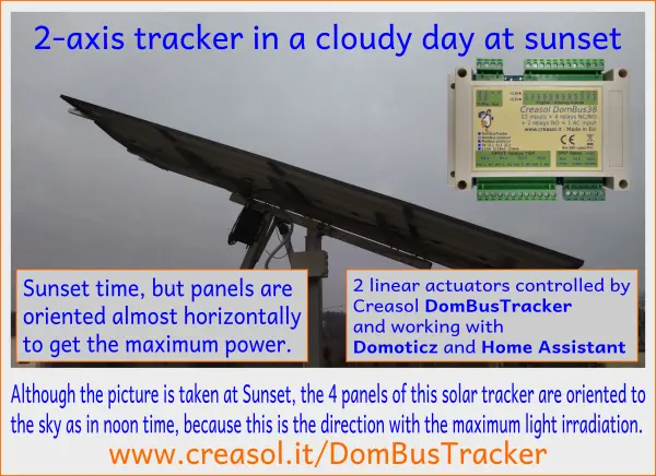
- Utilizza un sensore solare standard impermeabile composto da 4 fotodetectori, per determinare la migliore inclinazione/azimut anche in caso di nuvole.
- 4 relè da 10 A consentono di controllare 2 attuatori lineari con forza di 800 kg (o simili), alimentati da un alimentatore da 24 V (preferibilmente) o 12 V.
- Rilevamento della corrente per rilevare automaticamente i finecorsa interni dell'attuatore lineare .
- 2 ingressi collegabili a 2 pulsanti opzionali su/giù per muovere manualmente i motori
- 1 ingresso collegabile ad un interruttore opzionale per disattivare il tracciamento automatico
- Ulteriori 3 ingressi analogici/digitali, collegabili a NTC (solo IN10), contatori di energia, misuratore di velocità del vento, ...
- 2 relè aggiuntivi da 10A, per abilitare/disabilitare l'alimentatore (risparmiando sui consumi energetici durante la notte) e altro ancora.
- 1 ingresso optoisolato AC per rilevare (e segnalare) interruzioni di corrente
- Resistenza di terminazione del bus RS485 interna (150 ohm) che può essere abilitata tramite un ponticello PCB (con un saldatore)
- Bus RS485, che funziona con un cavo fino a 500 m (utilizzando cavo di allarme standard: 2x0,50+2x0,22mm² + schermatura)
- Contenitore a basso profilo per guida DIN, 115x90x40mm
- Morsettiere a innesto per un cablaggio semplice
- Parametri configurabili tramite bus RS485, per funzionare con quasi tutti i sistemi di tracciamento
- Disponibile con 2 firmware a scelta:
- Firmware DomBus , funzionante con Domoticz, che implementa il protocollo proprietario DomBus
- Firmware Modbus , compatibile con NodeRED, Home Assistant, OpenHAB e molti altri controller che supportano il protocollo Modbus standard.
- Consumo energetico molto basso : 15 mW con relè spenti.
- Kit fornito con 2 resistenze di potenza da 0,12 Ohm 5W per rilevamento corrente (per rilevare finecorsa interni al motore), 2 varistori 33V per evitare sovratensioni sulle bobine del motore e resistenza da 27 Ohm per alimentare il sensore sole.
Il sensore solare, gli attuatori, l'alimentatore da 24 V e la protezione fusibile devono essere acquistati separatamente .
Schema di collegamento
![]()
![]()
Capacità delle porte DomBusTracker (per la versione DomBus)
Indirizzo predefinito: 0xff38
| Port# | Name | Capabilities | Default configuration | Description |
| 1 | MN | OUT_DIGITAL | OUT_DIGITAL | SPDT 10A relay that have to be connected to the tilt linear actuator (North/South): see schematic below. Read-only: tracker position may be changed by using the Pns and Pew control bars. |
| 2 | MS | OUT_DIGITAL | OUT_DIGITAL | SPDT 10A relay that have to be connected to the tilt linear actuator (North/South): see schematic below. Read-only: tracker position may be changed by using the Pns and Pew control bars. |
| 3 | ME | OUT_DIGITAL | OUT_DIGITAL | SPDT 10A relay that have to be connected to the tilt linear actuator (East/West): see schematic below. Read-only: tracker position may be changed by using the Pns and Pew control bars. |
| 4 | MW | OUT_DIGITAL | OUT_DIGITAL | SPDT 10A relay that have to be connected to the tilt linear actuator (East/West): see schematic below. Read-only: tracker position may be changed by using the Pns and Pew control bars. |
| 5 | RL5 | OUT_DIGITAL | OUT_DIGITAL | 10A SPST relay (only NO contact), 250Vac or 30Vdc capability, that can be used for other purposes |
| 6 | RL6 | OUT_DIGITAL | OUT_DIGITAL | 10A SPST relay (only NO contact), 250Vac or 30Vdc capability, that can be used for other purposes |
| 7 | INAC | IN_AC, IN_COUNTER | IN_AC | Optoisolated input, that can be connected to a circuit breaker (to notify power outages, expecially useful for fridges and heat pumps), PIRs with 230V output (to monitor presence), light and appliances (to monitor when light or devices are ON). |
| 8 | N | IN_ANALOG | IN_ANALOG | North light sensor. |
| 9 | S | IN_ANALOG | IN_ANALOG | South light sensor. |
| 10 | E | IN_ANALOG | IN_ANALOG | East light sensor. |
| 11 | W | IN_ANALOG | IN_ANALOG | West light sensor. |
| 12 | Ins | IN_ANALOG | IN_ANALOG | North-South (tilt) motor current sensing (used to detect internal limit switches). Domoticz devices should be configured as IN_ANALOG,A=0.00042,TypeName=Current (Single) |
| 13 | Iew | IN_ANALOG | IN_ANALOG | North-South (tilt) motor current sensing (used to detect internal limit switches). Domoticz devices should be configured as IN_ANALOG,A=0.00042,TypeName=Current (Single) |
| 14 | Bns | IN_TWINBUTTON | IN_TWINBUTTON |
Analog input that can be connected to an optional external dual button (UP/DOWN connected together with a 10k resistor) to manually move the motor SN (elevation/tilt). |
| 15 | Bew | IN_TWINBUTTON | IN_TWINBUTTON |
Analog input that can be connected to an optional external dual button (UP/DOWN connected together with a 10k resistor) to manually move the motor EW (azimuth). |
| 16 | Sman | IN_DIGITAL | IN_DIGITAL | INVERTED |
Digital input that can be connected to an optional switch to disable automatic mode. It can be used for maintenance, or for blocking motors in a safe position before a storm in case that DomBusTracker is not managed by a domotic controller. |
| 17 | IN10 | IN_DIGITAL, IN_DIGITAL_PULLDOWN, IN_ANALOG, IN_TWINBUTTON, IN_COUNTER | IN_DIGITAL |
Analog or digital input, with optional 10k pullup (pcb jumper) and optional internal pulldown (activated when configured as IN_DIGITAL_PULLDOWN). |
| 18 | IN11 | IN_DIGITAL, IN_DIGITAL_PULLDOWN, IN_COUNTER | IN_DIGITAL |
Digital input, with internal pullup or optional internal pulldown (activated when configured as IN_DIGITAL_PULLDOWN). |
| 19 | IN12 | IN_DIGITAL, IN_DIGITAL_PULLDOWN, IN_COUNTER | IN_DIGITAL |
Digital input, with internal pullup or optional internal pulldown (activated when configured as IN_DIGITAL_PULLDOWN). |
| 20 | NS | CUSTOM | CUSTOM |
0-100% bar showing the deviation of the maximum NS radiation direction from the current tilt position |
| 21 | EW | CUSTOM | CUSTOM |
0-100% bar showing the deviation of the maximum EW radiation direction from the current azimuth position |
| 22 |
Pns |
CUSTOM | CUSTOM |
0-100% bar showing the current tilt position |
| 23 | Pew | CUSTOM | CUSTOM |
0-100% bar showing the current azimuth position |
| 24 | Man | OUT_DIGITAL | OUT_DIGITAL |
If Off, tracker is in automatic tracking mode. |
Funzionalità Modbus RTU di DomBusTracker (per la versione Modbus)
All'accensione, il modulo mostra sul LED rosso l'indirizzo slave Modbus corrente (indirizzo registro=8192) in formato decimale, sul LED verde la velocità in baud seriale (reg. 8193) e infine sul LED rosso la parità seriale (reg. 8194).
Se il valore è zero, viene emesso un lungo lampo.
Ad esempio, se reg(8192)=56, reg(8193)=0, reg(8194)=0, all'accensione verranno visualizzati i seguenti lampeggi del LED:
5 lampeggi rossi, pausa, 6 lampeggi rossi (indirizzo slave = 0x38 = 56 decimale), pausa, 1 lampeggio verde lungo (reg(8193)=0 => baudrate=115200bps), pausa, 1 lampeggio rosso lungo (reg(8194)=0 => parità=Nessuna).
Il dispositivo sarà operativo solo quando saranno mostrati i parametri indirizzo/baudrate/parità: il modulo accetterà quindi i comandi tramite Modbus RTU e mostrerà periodicamente lo stato di uscita per tutte le porte, dalla porta 1 alla porta massima: il lampeggio verde indica che lo stato della porta è spento, il lampeggio rosso indica che la porta è accesa.
Indirizzo slave predefinito: 56 (0x38)
| Addr | Name | Values | Description |
| 0 | MN | 0=OFF, 1=ON. Read only. Tracker position may be changed by using the Pns and Pew control bars. |
SPDT 10A relay that have to be connected to the tilt linear actuator (North/South): see schematic below. Read-only |
| 1 | MS |
0=OFF, 1=ON. Read only. |
SPDT 10A relay that have to be connected to the tilt linear actuator (North/South): see schematic below. Read-only |
| 2 | ME | 0=OFF, 1=ON. Read only. Tracker position may be changed by using the Pns and Pew control bars. |
SPDT 10A relay that have to be connected to the tilt linear actuator (East/West): see schematic below. Read-only |
| 3 | MW | 0=OFF, 1=ON. Read only. Tracker position may be changed by using the Pns and Pew control bars. |
SPDT 10A relay that have to be connected to the tilt linear actuator (East/West): see schematic below. Read-only |
| 4 | RL5 | 0=OFF, 1 or 65280=ON, 2-65279=ON for specified time. Logic can be inverted specifying the INVERTED option (on address 512+port) |
SPST 10A, that can be used for other purposes |
| 5 | RL6 | 0=OFF, 1 or 65280=ON, 2-65279=ON for specified time. Logic can be inverted specifying the INVERTED option (on address 512+port) |
SPST 10A, that can be used for other purposes |
| 6 | INAC | 0=OFF (floating), 1=ON (100-250V signal detected) | Optoisolated input, that can be connected to a circuit breaker (to notify power outages, expecially for fridges and heat pumps), PIRs with 230V output (to monitor presence), light and appliances (to monitor when light or devices are ON). |
| 7 | N | 0-65520 depending by the solar radiation received by this sensor. | North light sensor. |
| 8 | S | 0-65520 depending by the solar radiation received by this sensor. | South light sensor. |
| 9 | E | 0-65520 depending by the solar radiation received by this sensor. | East light sensor. |
| 10 | W | 0-65520 depending by the solar radiation received by this sensor. | West light sensor. |
| 11 | Ins | 0=OFF, >0 = 16-65520 if motor current is detected. Ins = value*0.00042 [A] in case that sensing resistor is 0.12Ohm |
North-South (tilt) motor current sensing (used to detect internal limit switches). Domoticz devices should be configured as IN_ANALOG,A=0.00042,TypeName=Current (Single) |
| 12 | Iew | 0=OFF, >0 = 16-65520 if motor current is detected. Ins = value*0.00042 [A] in case that sensing resistor is 0.12Ohm |
North-South (tilt) motor current sensing (used to detect internal limit switches). Domoticz devices should be configured as IN_ANALOG,A=0.00042,TypeName=Current (Single) |
| 13 | Bns | 0=OFF, 10=DOWN, 20=UP | Used to manually control the SN motor (for tilt/elevation) by an external UP/DOWN dual button |
| 14 | Bew | 0=OFF, 10=DOWN, 20=UP | Used to manually control the EW motor (for azimuth) by an external UP/DOWN dual button. |
| 15 | Sman | 0=AUTO, 1=MANUAL/STOP |
Used to manually disable motors by an external switch connected to GND: motor will be moved manually, by the Bns and Bew dual buttons, or by the Pns and Pew domotic controllers. |
| 16 | IN10 |
0=OFF, 1=ON. |
Analog or digital input, with optional 10k pullup (pcb jumper) and optional internal pulldown (activated when configured as IN_DIGITAL_PULLDOWN). |
| 17 | IN11 | 0=OFF, 1=ON. Logic can be inverted specifying the INVERTED option (on address 512+port) |
Digital input, with internal pullup or optional internal pulldown (activated when configured as IN_DIGITAL_PULLDOWN). |
| 18 | IN12 | 0=OFF, 1=ON. Logic can be inverted specifying the INVERTED option (on address 512+port). |
Digital input, with internal pullup or optional internal pulldown (activated when configured as IN_DIGITAL_PULLDOWN). |
| 19 | NS | 0=max radiation from the "North" side (minimum tilt). 100=max radiation from the "South" side (maximum tilt). |
0-100% bar showing the deviation of the maximum NS radiation direction from the current tilt position. |
| 20 | EW | 0=max radiation from East side. 100=max radiation from West side. |
0-100% bar showing the deviation of the maximum EW radiation direction from the current azimuth position |
| 21 |
Pns |
0=minimum tilt. 100=maximum tilt |
0-100% bar showing the current tilt position. Also, setting this register to a value between 0 and 100 automatically move the tracker to this position and set the register Man (23) to the value 1 (tracker in manual mode => no automatic tracker): in this case the automatic tracking function is disabled, useful to control the solar panel manually for example to lock the tracker in a safe position in case of hail or strong wind. |
| 22 | Pew | 0=minimum azimuth (East). 100=maximum azimuth (West) |
0-100% bar showing the current azimuth position. Also, setting this register to a value between 0 and 100 automatically move the tracker to this position and set the register Man (23) to the value 1 (tracker in manual mode => no automatic tracker): in this case the automatic tracking function is disabled, useful to control the solar panel manually for example to lock the tracker in a safe position in case of hail or strong wind. |
| 23 | Man | 0=Automatic mode. 1=Manual mode. |
If Off, tracker is in automatic tracking mode. |
| 255 | All input ports | bitmask: 1=> MN, 2=>MS, 4=>ME ... |
This address is used to check input state in one command |
| 256-273 | Port config | 1=OUT_DIGITAL, 2=OUT_RELAY_LP, ... |
Command used to configure port 1 (256), port 2 (257), ... as OUT_DIGITAL or OUT_RELAY_LP (low power consumption relay) or other value (see table below) |
| 512-529 | Port option | 0=NORMAL , 1=INVERTED (output normally ON, or input is ON when port voltage is 0V) | Set port option. If set to 1, output stays ON after boot until the port is asserted (then relays goes OFF). For inputs, setting INVERTED the port value is ON (1) when input voltage is 0V, OFF when input is left open with internal pullhigh enabled. |
| 8192 | Slave Address | 1-247 | Permits to change the slave address of the module, so it's possible to add other modules to the same bus |
| 8193 | Serial bitrate | 0=115200bps , 1=57600, 2=38400, 3=19200, 4=9600, 5=4800, 6=2400, 7=1200bps | Serial speed, default 115200 bps 8,n,1 |
| 8194 | Serial parity | 0=None , 1=Even, 2=Odd | Serial parity, default none (115200 bps 8,n,1) |
| 8198 | Revision, major | Read only | Get firmware version, major number. For example "02" means that revision is "02XX" where XX defined by parameter 8199 |
| 8199 | Revision, minor | Read only | Get firmware version, minor number. For example "h1" means that revision is "XXh1" where XX defined by parameter 8198 |
È possibile attivare una o più uscite per un determinato periodo di tempo (uscita monostabile/timer), come indicato in tabella. Il parametro corrispondente al tempo desiderato può essere calcolato utilizzando le seguenti regole:
Da 0 a 60 s => risoluzione 31,25 ms 2=62,5 ms, 3=93,75 ms, ... 1920=60 s => valore=tempo_in_millisecondi/31,5
Da 1m a 1h con risoluzione 1s 1921=61s, 3540+1920=5460=1h => valore=(tempo_in_secondi-60)+1920
Da 1h a 1g con risoluzione 1m 5461=1h+1m, 1380+5460=6840=24h => valore=(tempo_in_minuti-60)+5460
Da 1g a 1500 giorni con risoluzione di 1h 6841=25h, 6842=26h e così via => valore=(tempo_in_ore-24)+6840
Le tabelle seguenti mostrano alcuni esempi di comandi Modbus.
| Indirizzo slave | Codice funzionale | Indirizzo Reg. | Valore Reg. | Telaio | Descrizione |
| 56 | 06 | 8192 | 1 | [37][06][20][00][00][01][xx][xx] | Cambia l'indirizzo slave da 54 (0x36) a 1 |
| 01 | 06 | 8193 | 4 | [01] [06] [20] [01] [00] [04] [D2] [09] | Imposta la velocità seriale a 9600 bps |
| 01 | 06 | 8194 | 1 | [01] [06] [20] [02] [00] [01] [E2] [0A] | Imposta parità pari |
| 49 | 10 | 8192 | 1,4,1 | [31] [10] [20] [00] [00] [03] [06] [00] [01] [00] [04] [00] [01] [B1] [71] | Con un singolo comando, imposta l'indirizzo slave a 1, la velocità seriale a 9600 bps e la parità pari. In questo esempio, l'indirizzo originale del modulo era 49 (0x31). |
| 01 | 06 | 0 | 65280 | [01] [06] [00] [00] FF [00] [C8] [3A] | Attiva l'uscita RL1 per sempre (65280=0xff00) |
| 01 | 06 | 1 | 960 | [01][06][00][01][03][C0][D8][AA] | Attivare RL2 per 960/32=30s |
| 01 | 06 | 255 | 0 | [01][06][00][FF][00][00][B9][FA] | Disabilita tutte le uscite (Reg.Addr=255) |
| 01 | 10 | 0 | 32,0,0,65280 | [31] [10] [00] [00] [00] [04] [08] [00] 20 [00] [00] [00] [00] FF [00] E6 [5C] | Imposta RL1 su On per 1 s (32), RL2 su Off, RL3 su Off, RL4 su On - È possibile impostare al massimo 10 registri in un comando |
| 01 | 03 | 255 | 1 | [01] [03] [00] [FF] [00] [01] [B4] [3A] | Legge un valore a 16 bit con lo stato delle porte. Ad esempio, se il valore restituito è 0xd1 (0b11010001), lo stato dell'output è: RL8=Acceso, RL7=Acceso, RL6=Spento, RL5=Acceso, RL4=Spento, RL3=Spento, RL2=Spento, RL1=Acceso |
| 01 | 03 | 8198 | 2 | [01] [03] [20] [06] [00] [02] [2F] [CA] | Legge 4 byte all'interno della versione del modulo. Ad esempio, se il valore restituito è <30><32><68><31> (in formato esadecimale), il valore ASCII corrispondente è "02h1" (Firmware 02h1) |
| 01 | 0F | 0 | 8,1,0xd1 | [01] [0F] [00] [00] [00] [08] [01] [D1] [3E] [C9] | Imposta lo stato della bobina su 0xd1 (0b11010001), attivando RL8, RL7, RL5, RL1 e disabilitando altri relè |
| 01 | 01 | 0 | 8 | [01] [01] [00] [00] [00] [08] [3D] [CC] | Leggere lo stato della bobina. Se il valore restituito è 0xd1 (0b11010001), significa che RL8, RL7, RL5 e RL1 sono accesi. |
Il protocollo Modbus può essere testato facilmente utilizzando un programma Modbus, come mbpoll per Linux:
mbpoll -v -m rtu -0 -1 -a 1 -b 115200 -P nessuno -r 0 /dev/ttyUSB0 32 0 64 128 0 0 0 65280
per attivare RL1 per 1 s, R3 per 2 s, RL4 per 4 s e RL8 per sempre.
mbpoll -v -m rtu -0 -1 -a 1 -b 115200 -P nessuno -r 255 -c 1 /dev/ttyUSB0
per leggere tutti gli stati dei porti.
Parametri configurabili
I seguenti parametri possono essere configurati dall'utente per impostare i tempi di funzionamento del motore e far funzionare il tracker come preferito.
| Nome del parametro | Descrizione | Allineare | Predefinito | Impostazioni DomBus |
Indirizzo Modbus (solo scrittura) |
| Controllo del tracciamento periodico | Tempo di attesa prima di spostare nuovamente i motori, durante il tracciamento | 10-600 secondi | 120 | INIT=60 sulla porta Man (dispositivo virtuale di accensione/spegnimento manuale) | 10023 |
| Sensore di tracciamento minimo | Soglia per i sensori N+S per distinguere tra notte e giorno | 16-16384 | 2048 | INIT=2048 sulla porta MS (bobina motore S) | 10001 |
| TrackerNightTime | Tempo di attesa dal rilevamento notturno prima di passare alla posizione notturna | 60-43200 secondi | 1200 | INIT=600 sulla porta MW (bobina motore W) | 10003 |
| TrackerNightPercNS | Posizione di inclinazione notturna (0-100%) | 0-100 | 20 | INIT=20 sulla porta MN (bobina motore N) | 10000 |
| TrackerNightPercEW | Posizione azimutale notturna (0-100%) | 0-100 | 0 | INIT=0 sulla porta ME | 10002 |
| Orario di lavoroNS | Tempo di lavoro dell'attuatore di inclinazione | 10-600 secondi | 100 | INIT=100 sulla porta Pns (percentuale di posizione NS) | 10021 |
| Orario di lavoroEW | Tempo di lavoro dell'attuatore azimutale | 10-600 secondi | 100 | INIT=100 sulla porta Pew (percentuale di posizione EW) | 10022 |
| TrackerCurrentMinNS | Soglia per determinare se la corrente scorre attraverso il motore NS | 16÷16384 | 512 | INIT=512 sulla porta Ins (corrente misurata sul motore NS) | 10011 |
| TrackerCurrentMinEW | Soglia per determinare se la corrente scorre attraverso il motore EW | 16÷16384 | 512 | INIT=512 sulla porta Iew (corrente misurata sul motore EW) | 10012 |