Module domotique pouvant être utilisé comme tracker solaire autonome à axe simple ou double , fonctionnant de manière autonome.
Peut également être contrôlé par un système domotique , comme Domoticz (version DomBusTracker avec firmware protocole DomBus), Home Assistant, Node-RED, OpenHAB , ... (version DomBusTracker avec firmware protocole Modbus).
Veuillez sélectionner la page anglaise pour obtenir les informations originales les plus récentes.
Tracker solaire à deux axes
Le suiveur solaire est très bon pour les systèmes photovoltaïques car il améliore la production totale d'énergie et, de plus, augmente la puissance tôt le matin et en fin d' après-midi , lorsque l'énergie est plus chère et moins disponible.
Le graphique suivant montre la comparaison de l'énergie produite lors d'une journée ensoleillée, le 31 octobre 2024, dans le nord de l'Italie, entre un tracker solaire à 2 axes et un photovoltaïque sur le toit.
![]()
![]()
En comparant les deux systèmes, on peut dire que, dans ces conditions, le tracker 2 axes offre des performances presque trois fois supérieures à celles d'un système photovoltaïque sur toit. En temps normal, ses performances sont presque deux fois supérieures à celles d'un système photovoltaïque sur un toit orienté au sud, avec une inclinaison standard pour les maisons italiennes (environ 15 degrés). ![]() Vidéo YouTube
Vidéo YouTube
Ce contrôleur est basé sur le contrôleur chinois XMYC-3, utilisant le même capteur solaire, mais ajoutant quelques fonctionnalités comme la détection automatique des interrupteurs de fin de course à l'intérieur des moteurs (les actionneurs linéaires ont des interrupteurs de fin de course à l'intérieur, qui coupent l'alimentation), l'intégration du système domotique (vous pouvez choisir entre le protocole propriétaire DomBus fonctionnant avec Domoticz et le protocole standard Modbus fonctionnant avec presque tous les contrôleurs domotiques) et le retour automatique en position nuit.
![]()
Caractéristiques 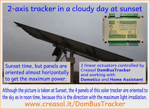
- Utilisez un capteur solaire étanche standard composé de 4 photodétecteurs, pour déterminer la meilleure inclinaison/azimut même en cas de nuages.
- 4 relais 10A permettent de contrôler 2 actionneurs linéaires d'une force de 800kg (ou similaire), alimentés par un bloc d'alimentation 24V (préféré) ou 12V.
- Détection de courant pour détecter automatiquement les interrupteurs de fin de course internes de l'actionneur linéaire .
- 2 entrées pouvant être connectées à 2 boutons haut/bas optionnels pour déplacer les moteurs manuellement
- 1 entrée pouvant être connectée à un interrupteur optionnel pour désactiver le suivi automatique
- 3 entrées analogiques/numériques supplémentaires, pouvant être connectées à NTC (uniquement IN10), compteurs d'énergie, compteur de vitesse du vent, ...
- 2 relais supplémentaires 10A, pour activer/désactiver le bloc d'alimentation (économie de consommation d'énergie pendant la nuit) et plus encore.
- 1x entrée optoisolée CA pour détecter (et signaler) les pannes de courant
- Résistance de terminaison de bus RS485 interne (150 ohms) pouvant être activée par un cavalier PCB (avec un fer à souder)
- Bus RS485, fonctionnant avec jusqu'à 500 m de câble (en utilisant un câble d'alarme standard : 2x0,50+2x0,22mm² + blindage)
- Boîtier à profil bas pour rail DIN, 115 x 90 x 40 mm
- Borniers enfichables pour un câblage facile
- Paramètres configurables par bus RS485, pour fonctionner avec presque tous les systèmes de suivi
- Disponible avec 2 firmwares au choix :
- Micrologiciel DomBus , fonctionnant avec Domoticz, implémentant le protocole propriétaire DomBus
- Micrologiciel Modbus , fonctionnant avec NodeRED, Home Assistant, OpenHAB et de nombreux autres contrôleurs prenant en charge le protocole Modbus standard.
- Très faible consommation : 15 mW avec relais OFF.
- Kit fourni avec 2 résistances de puissance 0,12 Ohm 5W pour la détection de courant (pour détecter les fins de course internes du moteur), 2 varistances 33V pour éviter les surtensions sur les bobines du moteur et une résistance de 27 Ohm pour alimenter le capteur solaire.
Le capteur solaire, les actionneurs, le bloc d'alimentation 24 V et la protection par fusible doivent être achetés séparément .
Schéma de connexion
![]()
![]()
Capacités des ports DomBusTracker (pour la version DomBus)
Adresse par défaut : 0xff38
| Port# | Name | Capabilities | Default configuration | Description |
| 1 | MN | OUT_DIGITAL | OUT_DIGITAL | SPDT 10A relay that have to be connected to the tilt linear actuator (North/South): see schematic below. Read-only: tracker position may be changed by using the Pns and Pew control bars. |
| 2 | MS | OUT_DIGITAL | OUT_DIGITAL | SPDT 10A relay that have to be connected to the tilt linear actuator (North/South): see schematic below. Read-only: tracker position may be changed by using the Pns and Pew control bars. |
| 3 | ME | OUT_DIGITAL | OUT_DIGITAL | SPDT 10A relay that have to be connected to the tilt linear actuator (East/West): see schematic below. Read-only: tracker position may be changed by using the Pns and Pew control bars. |
| 4 | MW | OUT_DIGITAL | OUT_DIGITAL | SPDT 10A relay that have to be connected to the tilt linear actuator (East/West): see schematic below. Read-only: tracker position may be changed by using the Pns and Pew control bars. |
| 5 | RL5 | OUT_DIGITAL | OUT_DIGITAL | 10A SPST relay (only NO contact), 250Vac or 30Vdc capability, that can be used for other purposes |
| 6 | RL6 | OUT_DIGITAL | OUT_DIGITAL | 10A SPST relay (only NO contact), 250Vac or 30Vdc capability, that can be used for other purposes |
| 7 | INAC | IN_AC, IN_COUNTER | IN_AC | Optoisolated input, that can be connected to a circuit breaker (to notify power outages, expecially useful for fridges and heat pumps), PIRs with 230V output (to monitor presence), light and appliances (to monitor when light or devices are ON). |
| 8 | N | IN_ANALOG | IN_ANALOG | North light sensor. |
| 9 | S | IN_ANALOG | IN_ANALOG | South light sensor. |
| 10 | E | IN_ANALOG | IN_ANALOG | East light sensor. |
| 11 | W | IN_ANALOG | IN_ANALOG | West light sensor. |
| 12 | Ins | IN_ANALOG | IN_ANALOG | North-South (tilt) motor current sensing (used to detect internal limit switches). Domoticz devices should be configured as IN_ANALOG,A=0.00042,TypeName=Current (Single) |
| 13 | Iew | IN_ANALOG | IN_ANALOG | North-South (tilt) motor current sensing (used to detect internal limit switches). Domoticz devices should be configured as IN_ANALOG,A=0.00042,TypeName=Current (Single) |
| 14 | Bns | IN_TWINBUTTON | IN_TWINBUTTON |
Analog input that can be connected to an optional external dual button (UP/DOWN connected together with a 10k resistor) to manually move the motor SN (elevation/tilt). |
| 15 | Bew | IN_TWINBUTTON | IN_TWINBUTTON |
Analog input that can be connected to an optional external dual button (UP/DOWN connected together with a 10k resistor) to manually move the motor EW (azimuth). |
| 16 | Sman | IN_DIGITAL | IN_DIGITAL | INVERTED |
Digital input that can be connected to an optional switch to disable automatic mode. It can be used for maintenance, or for blocking motors in a safe position before a storm in case that DomBusTracker is not managed by a domotic controller. |
| 17 | IN10 | IN_DIGITAL, IN_DIGITAL_PULLDOWN, IN_ANALOG, IN_TWINBUTTON, IN_COUNTER | IN_DIGITAL |
Analog or digital input, with optional 10k pullup (pcb jumper) and optional internal pulldown (activated when configured as IN_DIGITAL_PULLDOWN). |
| 18 | IN11 | IN_DIGITAL, IN_DIGITAL_PULLDOWN, IN_COUNTER | IN_DIGITAL |
Digital input, with internal pullup or optional internal pulldown (activated when configured as IN_DIGITAL_PULLDOWN). |
| 19 | IN12 | IN_DIGITAL, IN_DIGITAL_PULLDOWN, IN_COUNTER | IN_DIGITAL |
Digital input, with internal pullup or optional internal pulldown (activated when configured as IN_DIGITAL_PULLDOWN). |
| 20 | NS | CUSTOM | CUSTOM |
0-100% bar showing the deviation of the maximum NS radiation direction from the current tilt position |
| 21 | EW | CUSTOM | CUSTOM |
0-100% bar showing the deviation of the maximum EW radiation direction from the current azimuth position |
| 22 |
Pns |
CUSTOM | CUSTOM |
0-100% bar showing the current tilt position |
| 23 | Pew | CUSTOM | CUSTOM |
0-100% bar showing the current azimuth position |
| 24 | Man | OUT_DIGITAL | OUT_DIGITAL |
If Off, tracker is in automatic tracking mode. |
Fonctionnalités Modbus RTU de DomBusTracker (pour la version Modbus)
A la mise sous tension, le module affiche sur la LED rouge l'adresse esclave Modbus actuelle (adresse du registre = 8192) au format décimal, sur la LED verte le débit en bauds série (reg. 8193), et enfin sur la LED rouge la parité série (reg. 8194).
Si une valeur est nulle, un long flash est émis.
Par exemple, si reg(8192)=56, reg(8193)=0, reg(8194)=0, à la mise sous tension, les clignotements LED suivants seront affichés :
5 clignotements rouges, pause, 6 clignotements rouges (adresse esclave = 0x38 = 56 décimal), pause, 1 long clignotement vert (reg(8193)=0 => débit en bauds=115200bps), pause, 1 long clignotement rouge (reg(8194)=0 => parité=Aucune).
L'appareil ne sera opérationnel que lorsque les paramètres d'adresse/débit en bauds/parité auront été affichés : le module acceptera alors les commandes de Modbus RTU et affichera périodiquement l'état de sortie de tous les ports, de 1 au port max : un clignotement vert signifie que l'état du port est désactivé, un clignotement rouge signifie que le port est activé.
Adresse esclave par défaut : 56 (0x38)
| Addr | Name | Values | Description |
| 0 | MN | 0=OFF, 1=ON. Read only. Tracker position may be changed by using the Pns and Pew control bars. |
SPDT 10A relay that have to be connected to the tilt linear actuator (North/South): see schematic below. Read-only |
| 1 | MS |
0=OFF, 1=ON. Read only. |
SPDT 10A relay that have to be connected to the tilt linear actuator (North/South): see schematic below. Read-only |
| 2 | ME | 0=OFF, 1=ON. Read only. Tracker position may be changed by using the Pns and Pew control bars. |
SPDT 10A relay that have to be connected to the tilt linear actuator (East/West): see schematic below. Read-only |
| 3 | MW | 0=OFF, 1=ON. Read only. Tracker position may be changed by using the Pns and Pew control bars. |
SPDT 10A relay that have to be connected to the tilt linear actuator (East/West): see schematic below. Read-only |
| 4 | RL5 | 0=OFF, 1 or 65280=ON, 2-65279=ON for specified time. Logic can be inverted specifying the INVERTED option (on address 512+port) |
SPST 10A, that can be used for other purposes |
| 5 | RL6 | 0=OFF, 1 or 65280=ON, 2-65279=ON for specified time. Logic can be inverted specifying the INVERTED option (on address 512+port) |
SPST 10A, that can be used for other purposes |
| 6 | INAC | 0=OFF (floating), 1=ON (100-250V signal detected) | Optoisolated input, that can be connected to a circuit breaker (to notify power outages, expecially for fridges and heat pumps), PIRs with 230V output (to monitor presence), light and appliances (to monitor when light or devices are ON). |
| 7 | N | 0-65520 depending by the solar radiation received by this sensor. | North light sensor. |
| 8 | S | 0-65520 depending by the solar radiation received by this sensor. | South light sensor. |
| 9 | E | 0-65520 depending by the solar radiation received by this sensor. | East light sensor. |
| 10 | W | 0-65520 depending by the solar radiation received by this sensor. | West light sensor. |
| 11 | Ins | 0=OFF, >0 = 16-65520 if motor current is detected. Ins = value*0.00042 [A] in case that sensing resistor is 0.12Ohm |
North-South (tilt) motor current sensing (used to detect internal limit switches). Domoticz devices should be configured as IN_ANALOG,A=0.00042,TypeName=Current (Single) |
| 12 | Iew | 0=OFF, >0 = 16-65520 if motor current is detected. Ins = value*0.00042 [A] in case that sensing resistor is 0.12Ohm |
North-South (tilt) motor current sensing (used to detect internal limit switches). Domoticz devices should be configured as IN_ANALOG,A=0.00042,TypeName=Current (Single) |
| 13 | Bns | 0=OFF, 10=DOWN, 20=UP | Used to manually control the SN motor (for tilt/elevation) by an external UP/DOWN dual button |
| 14 | Bew | 0=OFF, 10=DOWN, 20=UP | Used to manually control the EW motor (for azimuth) by an external UP/DOWN dual button. |
| 15 | Sman | 0=AUTO, 1=MANUAL/STOP |
Used to manually disable motors by an external switch connected to GND: motor will be moved manually, by the Bns and Bew dual buttons, or by the Pns and Pew domotic controllers. |
| 16 | IN10 |
0=OFF, 1=ON. |
Analog or digital input, with optional 10k pullup (pcb jumper) and optional internal pulldown (activated when configured as IN_DIGITAL_PULLDOWN). |
| 17 | IN11 | 0=OFF, 1=ON. Logic can be inverted specifying the INVERTED option (on address 512+port) |
Digital input, with internal pullup or optional internal pulldown (activated when configured as IN_DIGITAL_PULLDOWN). |
| 18 | IN12 | 0=OFF, 1=ON. Logic can be inverted specifying the INVERTED option (on address 512+port). |
Digital input, with internal pullup or optional internal pulldown (activated when configured as IN_DIGITAL_PULLDOWN). |
| 19 | NS | 0=max radiation from the "North" side (minimum tilt). 100=max radiation from the "South" side (maximum tilt). |
0-100% bar showing the deviation of the maximum NS radiation direction from the current tilt position. |
| 20 | EW | 0=max radiation from East side. 100=max radiation from West side. |
0-100% bar showing the deviation of the maximum EW radiation direction from the current azimuth position |
| 21 |
Pns |
0=minimum tilt. 100=maximum tilt |
0-100% bar showing the current tilt position. Also, setting this register to a value between 0 and 100 automatically move the tracker to this position and set the register Man (23) to the value 1 (tracker in manual mode => no automatic tracker): in this case the automatic tracking function is disabled, useful to control the solar panel manually for example to lock the tracker in a safe position in case of hail or strong wind. |
| 22 | Pew | 0=minimum azimuth (East). 100=maximum azimuth (West) |
0-100% bar showing the current azimuth position. Also, setting this register to a value between 0 and 100 automatically move the tracker to this position and set the register Man (23) to the value 1 (tracker in manual mode => no automatic tracker): in this case the automatic tracking function is disabled, useful to control the solar panel manually for example to lock the tracker in a safe position in case of hail or strong wind. |
| 23 | Man | 0=Automatic mode. 1=Manual mode. |
If Off, tracker is in automatic tracking mode. |
| 255 | All input ports | bitmask: 1=> MN, 2=>MS, 4=>ME ... |
This address is used to check input state in one command |
| 256-273 | Port config | 1=OUT_DIGITAL, 2=OUT_RELAY_LP, ... |
Command used to configure port 1 (256), port 2 (257), ... as OUT_DIGITAL or OUT_RELAY_LP (low power consumption relay) or other value (see table below) |
| 512-529 | Port option | 0=NORMAL , 1=INVERTED (output normally ON, or input is ON when port voltage is 0V) | Set port option. If set to 1, output stays ON after boot until the port is asserted (then relays goes OFF). For inputs, setting INVERTED the port value is ON (1) when input voltage is 0V, OFF when input is left open with internal pullhigh enabled. |
| 8192 | Slave Address | 1-247 | Permits to change the slave address of the module, so it's possible to add other modules to the same bus |
| 8193 | Serial bitrate | 0=115200bps , 1=57600, 2=38400, 3=19200, 4=9600, 5=4800, 6=2400, 7=1200bps | Serial speed, default 115200 bps 8,n,1 |
| 8194 | Serial parity | 0=None , 1=Even, 2=Odd | Serial parity, default none (115200 bps 8,n,1) |
| 8198 | Revision, major | Read only | Get firmware version, major number. For example "02" means that revision is "02XX" where XX defined by parameter 8199 |
| 8199 | Revision, minor | Read only | Get firmware version, minor number. For example "h1" means that revision is "XXh1" where XX defined by parameter 8198 |
Il est possible d'activer une ou plusieurs sorties pendant une durée déterminée (sortie monostable/temporisée), comme indiqué dans le tableau. Le paramètre correspondant à la durée requise peut être calculé selon les règles suivantes :
De 0 à 60 s => résolution de 31,25 ms 2 = 62,5 ms, 3 = 93,75 ms, ... 1920 = 60 s => valeur = temps_en_millisecondes/31,5
De 1m à 1h avec une résolution de 1s 1921=61s, 3540+1920=5460=1h => valeur=(time_in_seconds-60)+1920
De 1h à 1j avec une résolution de 1m 5461=1h+1m, 1380+5460=6840=24h => valeur=(time_in_minutes-60)+5460
De 1j à 1500 jours avec une résolution de 1h 6841=25h, 6842=26h, et ainsi de suite => valeur=(time_in_hours-24)+6840
Les tableaux suivants présentent quelques exemples de commandes Modbus.
| Adresse de l'esclave | Code de fonction | Adresse registrée | Valeur Reg. | Cadre | Description |
| 56 | 06 | 8192 | 1 | [37][06][20][00][00][01][xx][xx] | Changer l'adresse de l'esclave de 54 (0x36) à 1 |
| 01 | 06 | 8193 | 4 | [01][06][20][01][00][04][D2][09] | Régler la vitesse série à 9600 bps |
| 01 | 06 | 8194 | 1 | [01][06][20][02][00][01][E2][0A] | Définir une parité paire |
| 49 | 10 | 8192 | 1,4,1 | [31] [10] [20] [00] [00] [03] [06] [00] [01] [00] [04] [00] [01] [B1] [71] | Avec une seule commande, définissez l'adresse de l'esclave sur 1, la vitesse série sur 9 600 bit/s et la parité paire. Dans cet exemple, l'adresse d'origine du module était 49 (0x31). |
| 01 | 06 | 0 | 65280 | [01][06][00][00][FF][00][C8][3A] | Activer la sortie RL1 pour toujours (65280=0xff00) |
| 01 | 06 | 1 | 960 | [01][06][00][01][03][C0][D8][AA] | Activer RL2 pendant 960/32=30s |
| 01 | 06 | 255 | 0 | [01][06][00][FF][00][00][B9][FA] | Désactiver toutes les sorties (Reg.Addr=255) |
| 01 | 10 | 0 | 32,0,0,65280 | [31] [10] [00] [00] [00] [04] [08] [00] [20] [00] [00] [00] [00] [FF] [00] [E6] [5C] | Réglez RL1 sur On pendant 1 s (32), RL2 sur Off, RL3 sur Off, RL4 sur On - Un maximum de 10 registres peuvent être définis en une seule commande |
| 01 | 03 | 255 | 1 | [01][03][00][FF][00][01][B4][3A] | Lire une valeur 16 bits avec l'état des ports. Par exemple, si la valeur renvoyée est 0xd1 (0b11010001), l'état de sortie est : RL8 = Activé, RL7 = Activé, RL6 = Désactivé, RL5 = Activé, RL4 = Désactivé, RL3 = Désactivé, RL2 = Désactivé, RL1 = Activé |
| 01 | 03 | 8198 | 2 | [01][03][20][06][00][02][2F][CA] | Lire 4 octets dans la version du module. Par exemple, si la valeur renvoyée est <30><32><68><31> (au format hexadécimal), la valeur ASCII correspondante est « 02h1 » (firmware 02h1). |
| 01 | 0F | 0 | 8,1,0xd1 | [01][0F][00][00][00][08][01][D1][3E][C9] | Réglez l'état de la bobine sur 0xd1 (0b11010001), activant RL8, RL7, RL5, RL1 et désactivant les autres relais |
| 01 | 01 | 0 | 8 | [01][01][00][00][00][08][3D][CC] | Lire l'état de la bobine. Si la valeur renvoyée est 0xd1 (0b11010001), cela signifie que RL8, RL7, RL5 et RL1 sont activés. |
Le protocole Modbus peut être testé facilement à l'aide d'un programme Modbus, comme mbpoll pour Linux :
mbpoll -v -m rtu -0 -1 -a 1 -b 115200 -P aucun -r 0 /dev/ttyUSB0 32 0 64 128 0 0 0 65280
pour activer RL1 pendant 1s, R3 pendant 2s, RL4 pendant 4s et RL8 pour toujours.
mbpoll -v -m rtu -0 -1 -a 1 -b 115200 -P aucun -r 255 -c 1 /dev/ttyUSB0
pour lire tous les états du port.
Paramètres configurables
Les paramètres suivants peuvent être configurés par l'utilisateur pour définir les temps de fonctionnement du moteur et faire fonctionner le tracker comme il le souhaite.
| Nom du paramètre | Description | Gamme | Défaut | Paramètres DomBus |
Adresse Modbus (écriture seule) |
| Vérification périodique du suivi | Temps d'attente avant de déplacer à nouveau les moteurs, pendant le suivi | 10 à 600 secondes | 120 | INIT=60 sur le port Man (périphérique virtuel activé/désactivé manuellement) | 10023 |
| TrackerSensorMin | Seuil pour les capteurs N+S permettant de distinguer la nuit du jour | 16-16384 | 2048 | INIT=2048 sur le port MS (bobine du moteur S) | 10001 |
| TrackerNightTime | Temps d'attente depuis la détection de nuit avant de passer en position de nuit | 60-43200 secondes | 1200 | INIT=600 sur le port MW (bobine W du moteur) | 10003 |
| TrackerNightPercNS | Position d'inclinaison nocturne (0-100%) | 0-100 | 20 | INIT=20 sur le port MN (bobine du moteur N) | 10000 |
| TrackerNightPercEW | Position azimutale nocturne (0-100%) | 0-100 | 0 | INIT=0 sur le port ME | 10002 |
| Temps de travailNS | Temps de fonctionnement de l'actionneur d'inclinaison | 10 à 600 secondes | 100 | INIT=100 sur le port Pns (Pourcentage de position NS) | 10021 |
| Temps de travailEW | Temps de fonctionnement de l'actionneur azimutal | 10 à 600 secondes | 100 | INIT=100 sur le port Pew (Pourcentage de position EW) | 10022 |
| TrackerCurrentMinNS | Seuil permettant de déterminer si le courant circule dans le moteur NS | 16÷16384 | 512 | INIT=512 sur le port Ins (courant mesuré sur le moteur NS) | 10011 |
| TrackerCurrentMinEW | Seuil permettant de déterminer si le courant circule dans le moteur EW | 16÷16384 | 512 | INIT=512 sur le port Iew (courant mesuré sur le moteur EW) | 10012 |