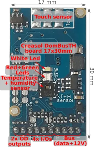
Creasol DomBusTH is a fully configurable small electronic board, 32x17mm, that can fit any blank cover with a 3.5mm hole in the centre, needed by the thermal/humidity sensor to exchange air with the room and to get the 3 LEDs light out. It can be connected to a Domoticz controller using the DomBus protocol, and other contollers (Node-RED, HomeAssistant, OpenHAB, ...) using the standard Modbus protocol by RS485 serial bus (using a standard alarm cable with 4 wires, 2 for 12/24V power supply, and 2 for data at 115200bps). Available in both DomBus and Modbus protocols
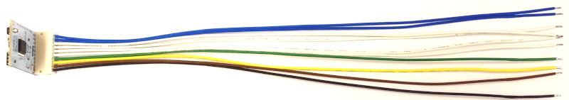
Th e electronic board is supplied with a 20cm long, 10 wires, assembly cable with plugin connector, so it's easy to connect the device to pushbuttons, switches, relays, ...
As other DomBus devices, DomBusTH minimizes power consumption, is automatically detected by Domoticz, and each port is fully web configurable via Domoticz device description or by Modbus protocol. Each module has a factory-programmed address that should be changed to a unique address when connected to the bus. Each port can be configured by software as digital inputs, analog inputs, digital outputs, dimmer, buzzer, blind, distance sensors, ...
It supports two different protocols (at puchase time, select the needed protocol!):
- DomBus protocol, that is supported by Domoticz home automation controller, is a reliable multi-master protocol that permits to manage dozens of modules and get status from a module as soon as it changes. Also it includes the so-called DCMD commands that, similarly to KNX, are transmitted between DomBus modules in the same bus to activate outputs, scenes and groups in case of events without needing for the intervention of the home automation controller, useful solution to get a home automation system working even in case of domotic controller fault. Check below for an explanation about DCMD.
The Creasol DomBus plugin have to be installed in Domoticz, using the Python Plugin Manager or downloading the software from GitHub (see the section below). - Modbus RTU protocol, widely used in industrial and home automation systems, is supported by almost any domotic controller like Home Assistant, OpenHAB, IObroker, Node-RED, ...
Modbus is a master-slave protocol that permits to activate and deactivate a single relay or a group of relays by a single command. Also, it's possible to specify, for each relay, the ON time from 31.5ms to 1500 days, so the relay automatically switches OFF after the selected time.
Confused about the two versions? If you use Domoticz, DomBus version is much better because includes enhanced features like DCMD and devices autodiscovery. For other building automations, Modbus version should be chosen because compatible with almost everything.
Ask for support on Telegram group https://t.me/DomBus
The RS485 serial bus is the ideal solution to get:
- easy wiring and connection: use a common thin alarm cable within 4 wires, 2x0.5mm² wires for 12V power supply, and 2x0.22mm² wires for data. This is much easier and better than ethernet UTP/STP connections.
- robustness differential signalling permits to connect about 30 modules with more than 200m total distance. Modules can be connected together using a mix of linear/star bus topology.
- very low power consumption: each module is supplied at 12V and has inside an high efficiency switching mode converter to minimize the power comsumption.
- power outage tolerant: using a 13.6V power supply with lead acid battery it's possible to supply domotic network, IPCams, NVR, switches, routers, so the system keeps working even in case of power cut-out.
- no RF pollution, no batteries to change
For large building, to improve the bus reliability, it's possible to make more than 1 bus so in case of fault, only the bus with fault stops working.
The bus must have two terminating resistors, on the bus ends: DomBus modules have the possibility to enable a 150 ohm resistor by shorting the Rbus (or RB) PCB jumper on the board.
Features
- temperature sensor, factory calibrated with a precisoin of +/- 0.3°C
- relative humidity sensor, factory calibrated with a precison of +/- 2%RH
- touch sensor in the top part,that can be used as a touch button/switch to toggle lights, appliances, functions, ... Distance from the finger should be 2mm max, so it's ok to install the board on a 1mm thickness plastic cover.
- 4 wires that can be configured as digital inputs, analog inputs, 1mA digital outputs and buzzer, distance sensors
- 2 open-drain outputs with 40V 100mA capability, that can be used to control external relays, electronic boards inputs with pullup, small LEDs (including the dimmer function), distance sensors.
- 1 analog input that measure the voltage on bus
- 1 red LED
- 1 green LED
- 1 white LED
- 7.5-35Vdc power supply (internally regulated by a switching mode power supply circuitry that minimize power consumption and dissipation)
- low power consumption: 2.5mA stand-by current at 13.6V
- 115200 bps RS485 bus (max length: 1km)
Changes from DomBusTH version 1
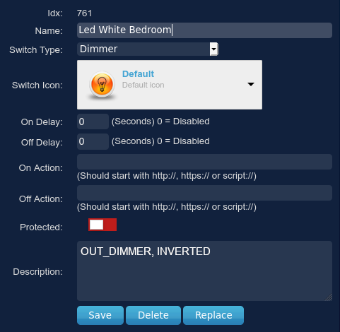
- LEDs have been invereted (active low, so the INVERTED option must be enabled on their configuration)
- touch sensor added to simulate a pushbutton switch
- the two open-drain outputs can be configured also as inputs, by PCB jumpers (for example, o5 jumper should be open and i5 jumper should be closed to configure IO5 as input)
- each input has a 10k pullup resistor to work with switches, double buttons (twinbutton), NTC 10k thermal sensors, alarm sensors, ... Also each input is protected by a 10k serie resistor and clamping diodes
- the analog input "ANIN Vbus" now can only measure Vbus voltage, cannot be connected elsewhere (other I/O can be configured as analog inputs to measure any DC voltage, directly or by external resistor partition)
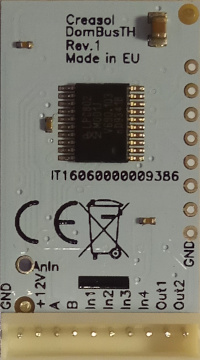
Cable
| N. | Color | Description |
| 1 | Black | Ground (0V) |
| 2 | Brown | Vbus (normally +12Vdc) |
| 3 | Yellow | RS485 A (data, 115200bps) |
| 4 | Green | RS485 B (data, 115200bps, inverted) |
| 5 | White | IO1: digital/analog input, counter, flasher, low power output, distance or NTC temperature sensor |
| 6 | White | IO2: digital/analog input, counter, flasher, low power output, distance or NTC temperature sensor |
| 7 | White | IO3: digital/analog input, counter, flasher, low power output, buzzer output, distance or NTC temperature sensor |
| 8 | White | IO4: digital/analog input, counter, flasher, low power output, buzzer output, distance or NTC temperature sensor |
| 9 | Blue | IO5: open drain output (active low: can be connected to a relay coil or LED katode, with other relay/led pin connected to positive voltage, +12V or +24V). Can also be configured as digital/analog input, counter, flasher, distance and NTC temperature sensor |
| 10 | Blue | IO6: open drain output (active low: can be connected to a relay coil or LED katode, with other relay/led pin connected to positive voltage, +12V or +24V). Can also be configured as digital/analog input, counter, flasher, distance and NTC temperature sensor |
DomBusTH Ports capabilities
Default address: 0xff51
| Port# | Name | Capabilities | Default configuration | Description |
| 1 | OUT1/IO5 | OUT_DIGITAL, OUT_RELAY_LP, OUT_DIMMER, OUT_BLIND, OUT_FLASH, IN_DIGITAL, IN_DIGITAL_PULLDOWN, IN_ANALOG, IN_COUNTER, DISTANCE | OUT_RELAY_LP | Open collector output, max 40V 100mA, that can be connected to external relay coil (DomRelay2 module), small led strip, other electronic device inputs that are active when shorted to GND, ... This kind of port is able only to pull down the output to GND, and have a varistor protecting output from going above 38-40V. Can also be configured as OUT_FLASH and connected to external Led or blinker (through a relay) to emit 1 or more flashes followed by 2s pause. It's designed to be connected to the DomRelay2 module (2 relay outputs). Can also be configured as input (open o5 jumper, and short i5 jumper) to be used as a digital input (with pullup or pulldown), analog input, counter, distance sensor. |
| 2 | OUT2/IO6 | OUT_DIGITAL, OUT_RELAY_LP, OUT_DIMMER, OUT_BLIND, OUT_FLASH, IN_DIGITAL, IN_DIGITAL_PULLDOWN, IN_ANALOG, IN_COUNTER, DISTANCE | OUT_RELAY_LP |
Open collector output, max 40V 100mA, that can be connected to external relay coil (DomRelay2 module), small led strip, other electronic device inputs that are active when shorted to GND, ... This kind of port is able only to pull down the output to GND, and have a varistor protecting output from going above 38-40V. |
| 3 | IO1 | IN_DIGITAL, IN_ANALOG, IN_TWINBUTTON, IN_COUNTER, DISTANCE | IN_TWINBUTTON | Input, with 10k protection resistor and 10k pullup, that can be used as digital input (active when shorted to GND), twinbutton input (special configuration that permits to connect two pushbuttons to a single input by a 10k resistor), analog input (remember there is a pullup resistor; in case that input voltage is greater than 3.3V, an external resistive divider must be added). Also, it can be connected to external NTC thermistor (10k B=3950) to measure a temperature, or waterproof ultrasonic distance sensor (with trigger connected to IO4) to measure a distance or water / liquid level. |
| 4 | IO2 | IN_DIGITAL, IN_ANALOG, IN_TWINBUTTON, IN_COUNTER, DISTANCE | IN_TWINBUTTON | Input, with 10k protection resistor and 10k pullup, that can be used as digital input (active when shorted to GND), twinbutton input (special configuration that permits to connect two pushbuttons to a single input by a 10k resistor), analog input (remember there is a pullup resistor; in case that input voltage is greater than 3.3V, an external resistive divider must be added). Also, it can be connected to external NTC thermistor (10k B=3950) to measure a temperature, or waterproof ultrasonic distance sensor (with trigger connected to IO4) to measure a distance or water / liquid level. |
| 5 | IO3 | IN_DIGITAL, IN_ANALOG, IN_TWINBUTTON, IN_COUNTER, DISTANCE, OUT_DIGITAL, OUT_BLIND, OUT_BUZZER | IN_TWINBUTTON | Input, with 10k protection resistor and 10k pullup, that can be used as digital input (active when shorted to GND), twinbutton input (special configuration that permits to connect two pushbuttons to a single input by a 10k resistor), analog input (remember there is a pullup resistor; in case that input voltage is greater than 3.3V, an external resistive divider must be added). Also, it can be connected to external NTC thermistor (10k B=3950) to measure a temperature, or waterproof ultrasonic distance sensor (with trigger connected to IO4) to measure a distance or water / liquid level. This port can be configured as output (enabling a 150 ohm output resistor by shorting o3 PCB jumper) and used as a digital output, blind output, or piezoelectric buzzer (buzzer without the oscillator inside, connected between IO3 and IO4). |
| 6 | IO4 | IN_DIGITAL, IN_ANALOG, IN_TWINBUTTON, IN_COUNTER, DISTANCE, OUT_DIGITAL, OUT_BLIND(1) | IN_TWINBUTTON | Input, with 10k protection resistor and 10k pullup, that can be used as digital input (active when shorted to GND), twinbutton input (special configuration that permits to connect two pushbuttons to a single input by a 10k resistor), analog input (remember there is a pullup resistor; in case that input voltage is greater than 3.3V, an external resistive divider must be added). Also, it can be connected to external NTC thermistor (10k B=3950) to measure a temperature. This port can be configured as output (enabling a 150 ohm output resistor by shorting o3 PCB jumper) and used as a digital output, blind output, or piezoelectric buzzer (buzzer without the oscillator inside, connected between IO3 and IO4). In case that one or more ultrasonic distance sensor are connected, the trigger input for those sensor should be connected to IO4 (with the PCB jumper o4 shorted). |
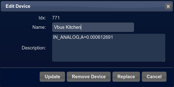
| 7 | ANIN Vbus | IN_ANALOG | IN_ANALOG | Used to monitor the voltage on DomBus power supply. The output value is by default from 0 to 65535. To convert in Domoticz the VALUE to a voltage, measure the Vbus voltage and set, in the description field, the parameter B=Vbus_VOLTAGE / VALUE (for example B=0.000611393) |
| 8 | Led Red | OUT_LEDSTATUS, OUT_DIGITAL, OUT_FLASH | OUT_LEDSTATUS,INVERTED | By default, it lights when a frame is transmitted to the serial bus. It can be configured as OUT_DIGITAL to get LED ON/OFF or OUT_FLASH: in this case the Led can be configured to stay ON for 250-2000ms, or send N flashes followed by 2s of pause. Very useful to show a status (alarm status, power consumption in kW, heating/cooling status, ...) |
| 9 | Led Green | OUT_DIGITAL, OUT_DIMMER, OUT_FLASH | OUT_FLASH,INVERTED | Configured by default as OUT_FLASH and used to show a status: it can be configured to stay ON for 250-2000ms, or send N flashes followed by 2s of pause. Very useful to show the alarm status, exported power in kW, heating/cooling status, ...) |
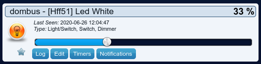
| 10 | Led White | OUT_DIGITAL, OUT_DIMMER, OUT_FLASH | OUT_DIMMER | Configured as OUT_DIGITAL to get LED ON/OFF. If the corresponding Domoticz device is configured as Selector Switch, it shows a number of flashes corresponding to the selector level/10: 0=Off, 10=1 flash, 20=2 flashes, 30=3 flashes, ... After the last flash, it waits 4 seconds before start flashing the next LED (if configured in the same way) or start flashing the same LED again. Even in the case it's configured as selector switch, if a Domoticz script Set Level to 1 the LED temporarily loose the flash function and turns solid ON: in this way it's possible to use a LED to notify a status, but in case of blackout it can be switched ON until power restores, like an emergency light. Can be configured as OUT_DIMMER, to vary the luminous intensity in 5% steps. |
| 11 | Temperature | SENSOR_TEMP | SENSOR_TEMP | Temperature sensor |
| 12 | Rel.Humidity | SENSOR_HUM | SENSOR_HUM | Relative humidity sensor |
| 13 | Temp+Hum | SENSOR_TEMP_HUM | SENSOR_TEMP_HUM | Domoticz sensor that shows both temperature and relative humidity in one place |
| 14 | Touch | IN_DIGITAL | IN_DIGITAL,INVERTED | Touch sensor, that works as a pushbutton switch by approching the finter near the top part of the board. |
(1): can be used as BLIND output, to open a blind/curtain, but only the previous port can be configured in Domoticz as OUT_BLIND because, when configured as OUT_BLIND, DomBus device automatically configure the next port to drive a relay in open direction.
DomBusTH Modbus RTU capabilities (for the Modbus version)
At power-on, the module shows on red LED the current Modbus slave address (register address=8192) in decimal format, on green LED the serial baudrate (reg. 8193), and finally on red LED the serial parity (reg. 8194).
If a value is zero, a long flash is emitted.
For example, if reg(8192)=81, reg(8193)=0, reg(8194)=0, at power the following led flashes will be shown:
8 red flashes, pause, 1 red flashes (slave address= 0x51 = 81 in decimal), pause, 1 long green flash (reg(8193)=0 => baudrate=115200bps), pause, 1 long red flash (reg(8194)=0 => parity=None).
Device will be operative only when address/baudrate/parity parameters have been shown: then module will accept commands by Modbus RTU, and periodically shows output status for all ports, from 1 to max port: green flash means that port status is Off, red flash means that port is On.
Default slave address: 81 (0x51)
| Addr | Name | Values | Description |
| 0 | IO5/OUT1 | 0=OFF (floating), 1=ON (output internally connected to GND), 2-65279=ON for the specified time (see below). | OpenDrain output that sink current (to GND): can be connected to a 5-24V relay coil, or to a led strip with 100mA max current. Can be configured as DIMMER output (0-100% with 5% step), or as input. See DomBus Ports capabilities table above. |
| 1 | IO5/OUT2 | 0=OFF (floating), 1=ON (output internally connected to GND), 2-65279=ON for the specified time (see below). | OpenDrain output that sink current (to GND): can be connected to a 5-24V relay coil, or to a led strip with 100mA max current. Can be configured as DIMMER output (0-100% with 5% step), or as input. See DomBus Ports capabilities table above. |
| 2 | IO1 | 0=OFF (input externally pulled/shorted to GND), 1=ON (input externally disconnected, with internal pullup to 3.3V). Logic level can be inverted with the INVERTED option (to be set on address 512+port) | Digital input, with internal 10k pullup. Can be configured as analog input, twinbutton, digital output. |
| 3 | IO2 | 0=OFF (input externally pulled/shorted to GND), 1=ON (input externally disconnected, with internal pullup to 3.3V). Logic can be inverted with the INVERTED option (to be set on address 512+port) | Digital input, with internal pullup. Can be configured as analog input, twinbutton, digital output. |
| 4 | IO3 | 0=OFF (floating), 1=ON (output internally connected to GND), 2-65279=ON for the specified time (see below). | Digital input, with internal pullup. Can be configured as analog input, twinbutton, digital output (PCB jumper permits to reduce output resistance), buzzer or flash |
| 5 | IO4 | 0=OFF (floating), 1=ON (output internally connected to GND), 2-65279=ON for the specified time (see below). | Digital input, with internal pullup. Can be configured as analog input, twinbutton, digital output (PCB jumper permits to reduce output resistance), buzzer or flash |
| 6 | Vbus | 16bit value in the range: 0=0V, 65532=36.3V |
Analog input internally connected to Vbus through a 1/11 resistive partition |
| 7 | LED Red | Led configured in flash mode: 0=OFF , 1=ON, N*10+M => sends N flashes, repeating for M times. If M=0, repeat N flashes forever. For example if value=30, transmits 3 pulses, wait 2s, then retransmit 3 pulses, ... If value=32, transmits 3 pulses for 2 times, then goes OFF. |
Led on the board. Can be configured as OUT_DIGITAL (OFF, ON, ON for the specified time) or DIMMER (0=OFF, 1=5%, ..., 20=100%) |
| 8 | LED Green | Led configured in flash mode: 0=OFF , 1=ON, N*10+M => sends N flashes, repeating for M times. If M=0, repeat N flashes forever. For example if value=30, transmits 3 pulses, wait 2s, then retransmit 3 pulses, ... If value=32, transmits 3 pulses for 2 times, then goes OFF. |
Led on the board. Can be configured as OUT_DIGITAL (OFF, ON, ON for the specified time) or DIMMER (0=OFF, 1=5%, ..., 20=100%) |
| 9 | LED White | Led configured in flash mode: 0=OFF , 1=ON, N*10+M => sends N flashes, repeating for M times. If M=0, repeat N flashes forever. For example if value=30, transmits 3 pulses, wait 2s, then retransmit 3 pulses, ... If value=32, transmits 3 pulses for 2 times, then goes OFF. |
Led on the board. Can be configured as OUT_DIGITAL (OFF, ON, ON for the specified time) or DIMMER (0=OFF, 1=5%, ..., 20=100%) |
| 10 | Temperature | 16 value that can be converted in this way: Temperature_Celsius=VALUE*0.1-50 °C |
Return the temperature measured every 15s by the sensor. Sensor is disabled for the first 3 minutes from power-ON, and when one or more LEDs are ON, to prevent heating effect |
| 11 | Rel.Humidity | 16 value that can be converted in this way: Relative_Humidity=VALUE*0.1 %RH |
Return the relative humidity measured every 15s by the sensor. Sensor is disabled for the first 3 minutes from power-ON, and when one or more LEDs are ON, to prevent heating effect |
| 13 | Touch | 0=finger not detected, 1=finger detected | Return the status of the touch sensor |
| 255 | All ports | bitmask: 1=> IO1, 2=>IO2, 3=>IO3 ... |
This address is used to set ON or OFF (no timer function) all outputs using a short command, by accumulating the bitmask for each output that should be ON: for example |
| 256-267 | Port config | 1=OUT_DIGITAL, 2=OUT_RELAY_LP, ... |
Command used to configure port 1 (256), port 2 (257), ... as OUT_DIGITAL or OUT_RELAY_LP (low power consumption relay) or other value (see table below) |
| 512-523 | Port option | 0=NORMAL, 1=INVERTED (output normally ON, or input is ON when port voltage is 0V) | Set port option. If set to 1, output stays ON after boot until the port is asserted (then relays goes OFF). For inputs, setting INVERTED the port value is ON (1) when input voltage is 0V, OFF when input is left open with internal pullhigh enabled. |
| 8192 | Slave Address | 1-247 | Permits to change the slave address of the module, so it's possible to add other modules to the same bus |
| 8193 | Serial bitrate | 0=115200bps, 1=57600, 2=38400, 3=19200, 4=9600, 5=4800, 6=2400, 7=1200bps | Serial speed, default 115200 bps 8,n,1 |
| 8194 | Serial parity | 0=None, 1=Even, 2=Odd | Serial parity, default none (115200 bps 8,n,1) |
| 8198 | Revision, major | Read only | Get firmware version, major number. For example "02" means that revision is "02XX" where XX defined by parameter 8199 |
| 8199 | Revision, minor | Read only | Get firmware version, minor number. For example "h1" means that revision is "XXh1" where XX defined by parameter 8198 |
It's possible to activate one or more outputs for a certain amount of time (monostable/timer output) as indicated in the table. The parameter corresponding to the needed time can be computed using the following rules:
From 0 to 60s => 31.25ms resolution 2=62.5ms, 3=93.75ms, ... 1920=60s => value=time_in_milliseconds/31.5
From 1m to 1h with 1s resolution 1921=61s, 3540+1920=5460=1h => value=(time_in_seconds-60)+1920
From 1h to 1d with 1m resolution 5461=1h+1m, 1380+5460=6840=24h => value=(time_in_minutes-60)+5460
From 1d to 1500 days with 1h resolution 6841=25h, 6842=26h, and so on => value=(time_in_hours-24)+6840
The following tables show some Modbus commands examples.
| Slave Addr | Func. Code | Reg.Addr | Reg.Value | Frame | Description |
| 81 | 06 | 8192 | 1 | [51][06][20][00][00][01][xx][xx] | Change slave address from 81 (0x51) to 1 |
| 01 | 06 | 8193 | 4 | [01][06][20][01][00][04][D2][09] | Set serial speed to 9600bps |
| 01 | 06 | 8194 | 1 | [01][06][20][02][00][01][E2][0A] | Set even parity |
| 49 | 10 | 8192 | 1,4,1 | [31][10][20][00][00][03][06][00][01][00][04][00][01][B1][71] | With a single command, set slave address to 1, serial speed to 9600bps, even parity. Original modules address was 49 (0x31) in this example. |
| 01 | 06 | 0 | 65280 | [01][06][00][00][FF][00][C8][3A] | Activate RL1 output forever (65280=0xff00) |
| 01 | 06 | 1 | 960 | [01][06][00][01][03][C0][D8][AA] | Activate RL2 for 960/32=30s |
| 01 | 06 | 255 | 0 | [01][06][00][FF][00][00][B9][FA] | Disable all outputs (Reg.Addr=255) |
| 01 | 10 | 0 | 32,0,0,65280 | [31][10][00][00][00][04][08][00][20][00][00][00][00][FF][00][E6][5C] | Set RL1 On for 1s (32), RL2 Off, RL3 Off, RL4 On - Max 10 registers can be set in one command |
| 01 | 03 | 255 | 1 | [01][03][00][FF][00][01][B4][3A] | Read a 16bit value with ports status. For example if returned value is 0xd1 (0b11010001), output status is: RL8=On, RL7=On, RL6=Off, RL5=On, RL4=Off, RL3=Off, RL2=Off, RL1=On |
| 01 | 03 | 8198 | 2 | [01][03][20][06][00][02][2F][CA] | Read 4 bytes within module version. For example, if returned value is <30><32><68><31> (in hex format), the corresponding ASCII value is "02h1" (Firmware 02h1) |
| 01 | 0F | 0 | 8,1,0xd1 | [01][0F][00][00][00][08][01][D1][3E][C9] | Set coil status to 0xd1 (0b11010001), activating RL8, RL7, RL5, RL1 and disabling other relays |
| 01 | 01 | 0 | 8 | [01][01][00][00][00][08][3D][CC] | Read coil status. If returned value is 0xd1 (0b11010001), it means that RL8, RL7, RL5 and RL1 are On |
Modbus protocol can be tested easily using a modbus program, like mbpoll for Linux:
mbpoll -v -m rtu -0 -1 -a1 -b115200 -Pnone -r 0 /dev/ttyUSB0 32 0 64 128 0 0 0 65280
to activate RL1 for 1s, R3 for 2s, RL4 for 4s and RL8 forever.
mbpoll -v -m rtu -0 -1 -a1 -b115200 -Pnone -r 255 -c 1 /dev/ttyUSB0
to read all port states.
Application notes
Connecting one ore more pushbutton switches
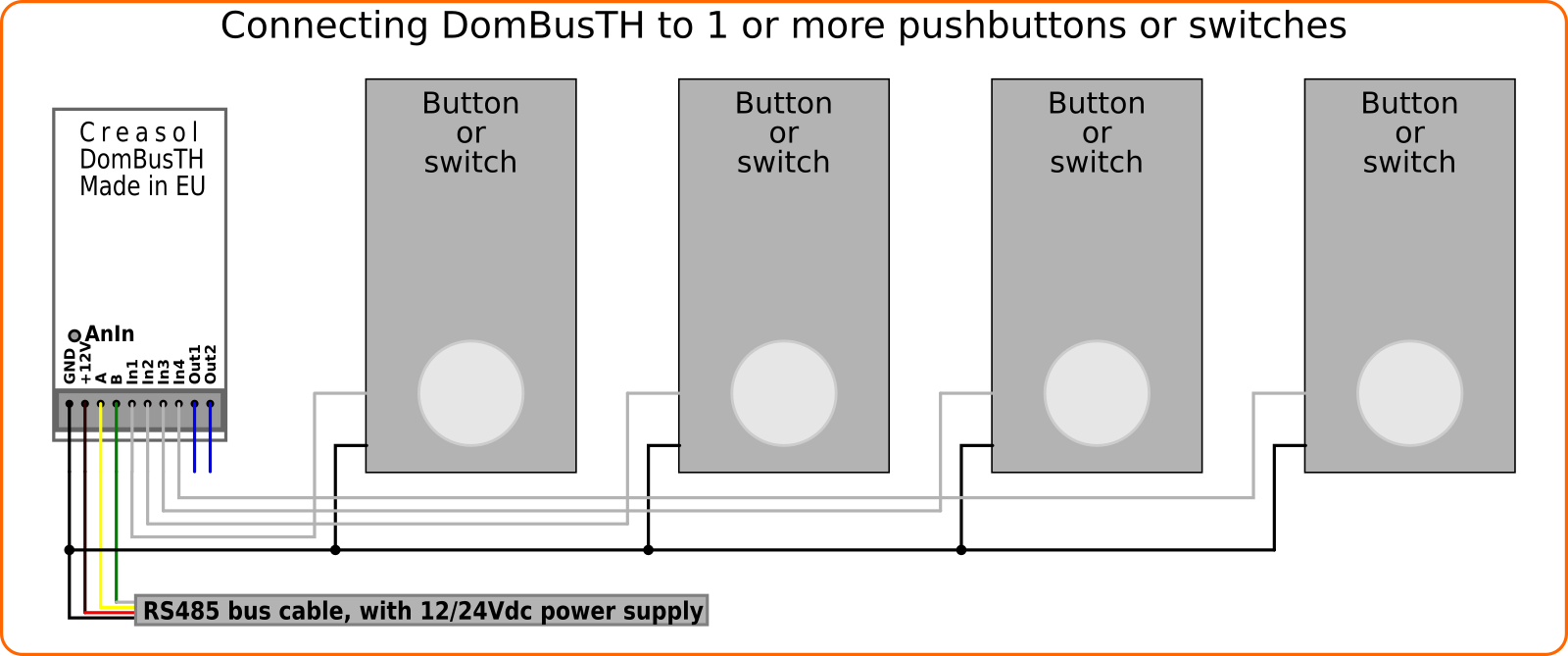
DomBusTH has 4 inputs, so it's possible to connect up to 4 pushbuttons or switches in this way. To connect more switches, see "twinbutton" section below.
Each input connected to the pushbutton/switch should be configured as IN_DIGITAL (On when open, Off when pushed/shorted) or IN_DIGITAL,INVERTED (On when pushed/shorted, Off when released/open).
Connecting two pushbutton switches to a single input (twinbutton)
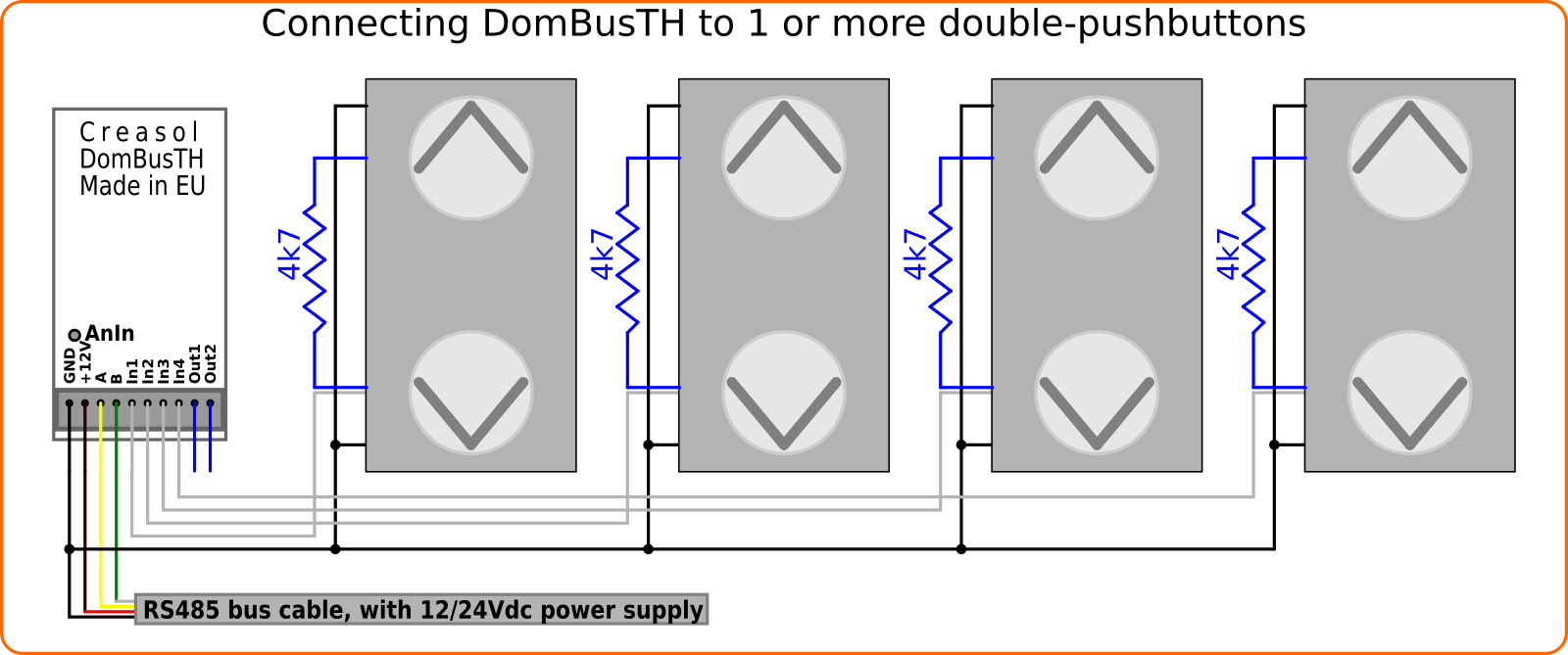
Configuring one input as IN_TWINBUTTON, it's possible to manage two pushbutton-switches by a single input. In this case, with 4 available inputs, it's possible to manage 4 double pushbuttons (totally 8 pushbuttons).
The two pushbutton-switches are connected together by a 4k7 resistor: in this way the DomBus device can determine if DOWN-pushbutton is pressed (input voltage = 0V) or UP-pushbutton is pressed (input voltage determined by the 4k7 external resistor and internal pullup resistor).
Please note that if UP and DOWN pushbuttons are pressed together, the DomBus device will read it as only DOWN button pushed.
Using red and green LEDs to show status of the photovoltaic
DomBusTH has 3 LEDs that can be configured as OUT_DIGITAL to switch ON or OFF as a normal light, and also they can be configured as OUT_FLASH and used to send notifications, sending 1 or more flashes followed by 2s of pause.
When the device is configured as OUT_FLASH, it's possible to send the value:
- 0 => Led OFF
- 1 => Led solid ON
- 2-9 => Led ON for (N-1)*250ms (2=>250ms, 3=>500ms, 5=>1s, 9=>2s)
- 10 => 1 flash followed by 2s pause, forever (until the port is programmed in another way)
- 11 => 1 flash followed by 2s pause, then OFF
- 12 => 1 flash followed by 2s pause, repeated twice, then OFF
- ... 19 => 1 flash followed by 2s pause, repeated for 9 times, then OFF
- 20 => 2 flashes followed by 2s pause, forever
- 21 => 2 flashes followed by 2s pause, only once
- ... and so on
This notification systems works with both Modbus and DomBus protocols: in the examble below, Domoticz has been programmed with 6 levels to permit LED to output up to 6 flashes corresponding to 0-5kW of power fed to the electric grid.

Also, this kind of notification can be set by DCMD commands, commands sent by DomBus module when an event occurs.
In the following video it's possible to see a DomBusTH device configured so
* white led shows the status of ventilation: 1 flash=renew air, 2 flashes=dehumidification, 3 flashes=renew+dehumidifcation (3 in this example)
* green led shows the current power fed, from photovoltaic, to the electric grid: 0=no power, 1 flash=up to 1kW, 2=up to 2kW, ... 6=up to 6kW (3 in this example, so the power fed to electric grid is between 2 and 3kW)
* red LED shows the power from the electric grid (0 in this example, so no red flashes).
Please note that a script that set the number of flashes on a LED configured as "selector switch" have to set the level to
| Level | Number of flashes |
| 0 | Always OFF |
| 1 | Always ON (solid ON) |
| 2-9 | On for (N-1)*250ms |
| 10 | 1 flash, then 2s pause |
| 20 | 2 flashes, than 2s pause |
| 30 | 3 flashes... and so on |
| N*10+M | N flashes, than 2s pause, repeated for M times |
LUA script that monitors electric grid voltage and power, and turn ON/OFF white LEDs in case of power outage
Click on https://www.creasol.it/support/domotics-home-automation-and-diy/141-domoticz-lua-script-that-check-and-manage-power-consumption to see what the LUA script script_device_power.lua does.
It checks the usage power (measured by a energy meter, like SDM230), automatically enable electric heaters (during the winter) or air dehumidifier (during the summer) in case of excessive phovotolatic power production (in case that selling surplus energy is not convenient), checks that electrical grid is connected activating available white LEDs (inside DomBusTH and externally connected) as emergency lights, prevent circuit breaking by disconnecting some loads/appliances and sending alerts when usage power raise above a threshold for more than N minutes, show on green/red LEDs some flashes corresponding to the produced/consumed power.
Configuring the analog input to measure the bus voltage used to supply DomBus devices
DomBusTH has one analog input internally connected to the bus positive wire (Vbus, normally 12-14V). This information can be used to measure the battery voltage, in case of power outage, disabling some devices (video surveillance, for example) when Pb battery voltage decreases below 12V.
DomBusTH send to Domoticz a integer 16bit number that must be multiplied by the constat value A to get the real voltage, so if the real voltage is 13.6V and shown value is 22197, A=13.6/22197=0.000612695 . Edit the device, in Domoticz, and put in the description IN_ANALOG,A=0.000612695 to show the real voltage value.
It's possible to use this analog in put to measure the voltage of another device: to do this open the PCB jumper marked "h" (by using a cutter) and solder a wire in the hole AnIn. It's possible to monitor voltages up to 30V. In case of higher voltage, additional serie resistance is needed to provide the needed voltage drop, but this value is beyond the scope of this section.
Configure one or more outputs as dimmer
It's possible to configure outputs as DIMMER: in this case a PWM 500Hz output is used to regulate the light intensity.
Device have to been configured as OUT_DIMMER and power regulated from 0 to 100%, with 5% step.
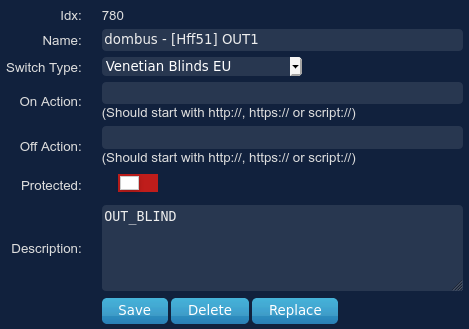
Configure outputs as blind (motor with UP/DOWN function)
Domoticz has a Venetian Blind type device that can be used to manage blinds or curtains: a single device can be used to open, close and stop the blind/curtain motor.
This type of device must be associated to two different relays, one for open and one for close direction.
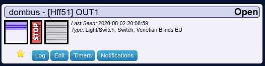
DomBusTH integrates this kind of management, so it's possible to configure Out1 as OUT_BLIND and in this way Out1 will be used to control the close direction relay, and the next output Out2 will be used to control the open direction relay.
Connecting a piezo buzzer to DomBusTH
Connect a piezo buzzer (without internal oscillator) to In3 and In4 I/O of DomBusTH, and configure In3 as OUT_BUZZER : in this way it's possible to enable a tone alert when In3 device is On.
Also, it's possible to configure the Domoticz In3 switch device as a Selector: in this way selecting level 0 buzzer will be OFF, selecting the next level (level=10) buzzer will be ON for a short pulse then OFF for 4 seconds; selecting level=20 the buzzer will be ON for 2 short pulses and then OFF for 4 seconds, and so on... This function, similar to Led alert explained above, can be useful to send an informational alert within a device status or a warning level.
To improve the buzzer volume, it's possible to reduce the output resistance of the I/O ports by shorting, with a solder iron, the PCB jumpers marked "a" and "b".
If the buzzer does not work, maybe it's a magnetic buzzer, maybe with the oscillator. Buzzers within the oscillator should be connected between 12V and the open-drain output OUT1 (or OUT2): configure OUT1 as OUT_DIGITAL, in this way it's possible to enable/disable buzzer.
To use the buzzer as a status notification, emitting 1 or more beeps invervalled by 4 seconds pause, set the Domoticz device (OUT1 port) as a Selector Switch, enabling level 10, 20, 30, 40, ... corresponding to 1 beep + pause, 2 beeps + pause, and so on.
An automation (script) can set the level to 10, 20, 30, ... to get 1 beep, 2 beeps, 3 beeps, ... on the buzzer.

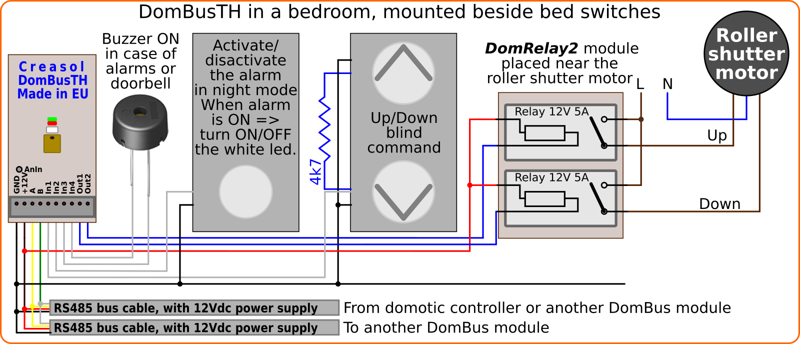
Installing DomBusTH near the bed switches, in the bedroom
The following diagram shows how it's possible to use DomBusTH in a bedroom to:
- measure the room temperature and humidity;
- control, by a pushbutton switch, the alarm system and white led:
alarm off, short pulse => enable night alarm and turn red Led ON for 2 seconds;
alarm on, short pulse => toggle white Led ON/OFF (can be used during the night to go bathroom without wake-up the partner);
alarm on, long pulse => disable alarm and turn green Led ON for 2 seconds; - control, by a double-pushbutton UP/DOWN, the roller shutters: two external relays are needed to drive the roller shutter motor UP/DOWN.
- buzzer alert in case of intrusion detection (alarm) and in case that someone ring the door bell.
Instead of using a button to enable/disable alarm and enable/disable the night led, it's possible to use the Touch sensor available in the current version of DomBusTH.
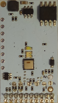
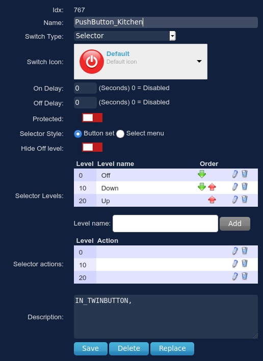
Using the Touch Sensor in the DomBusTH Rev.2
The new version of DomBusTH board, available since April 2023, integrates a touch sensor that permit to not loose a pushbutton space in the wall box. The following picture shows how to configure the touch sensor with Domoticz, by using the DCMD commands available in the DomBus protocol.
DCMD commands permit to execute operations in a easy way, without the need to write automations. In this case the Pulse (less than 0.5s) and Pulse2 (about 2s) triggers are used to toggle or activate two scenes, and also to activate a buzzer feedback.
Also, LEDs are programmed by a LUA script to show the current electricity power usage/return: red led flashes from 1 to N times to indicate a consumption up to N kW, conversely green led flashes from 1 to N times to indicate that exporting power is up to N kW (for example if green led flashes 4 times the exporting power is between 3 and 4 kW).
White LED is programmed to show the status of mechanical ventilation; also it will be solid-ON in case of power outage/blackout (acting as a weak emergency light).
LUA script for Domoticz are available at https://github.com/CreasolTech/domoticz_lua_scripts

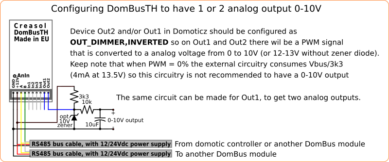
Circuit to convert DIMMER PWM outputs to 0-10V analog outputs
Adding 2 external resistors an 1 capacitor to one or both outputs, it's possible to get a 0-Vbus analog output suitable with 5% step, to control dimmer input of LED power supply for example. Alternatively, it's possible to use DomBus23 module that already have two precise 0-10V analog outputs with 1% step regulation, suitable to command LED stripe power supply units and other electronic boards that uses 0-10V input.
Normally Vbus is 12 or 13.5V, so when device output is 100%, output voltage corresponds with Vbus.
To get a 0-10V output, it's possible to add an extra 10V zener diode.
As written in the diagram below, this circuit is not really recommended, because when output is set to 0 the current consumption is about 4mA with Vbus=13.6V