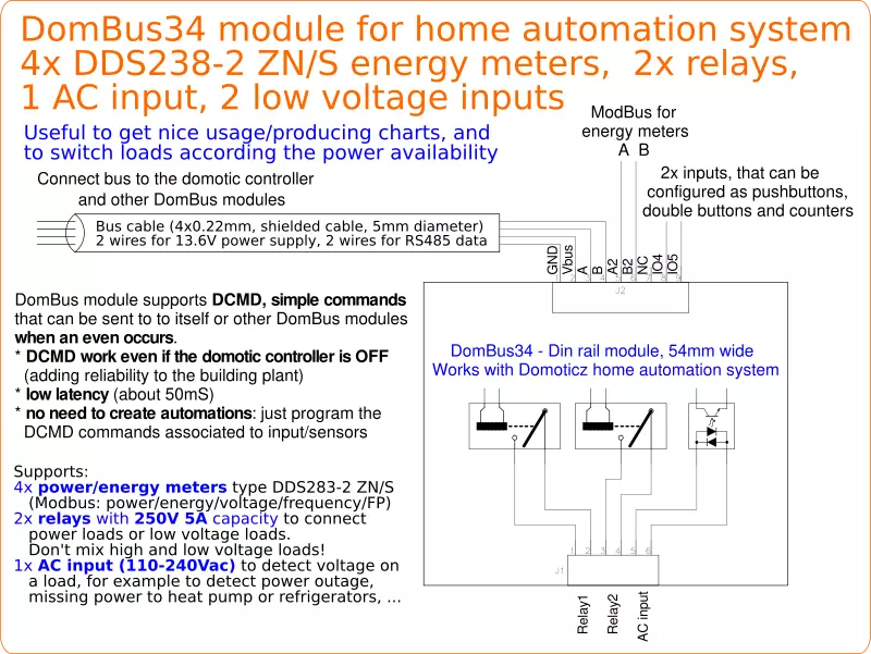
DomBus34 is a DIN-RAIL module, 54mm wide, designed to interface up to 4 power/energy meters, type DDS 238-2 ZN/S (Modbus), to measure power and energy (both imported and exported), voltage frequency and power factor.
It integrates 2 relay outputs 250V 5A SPST with overvoltage protection, 1 AC input 110-240Vac, and 2 low-voltage inputs that can be connected to pushbuttons and switches, double pushbuttons and counters.
It's designed to activate loads based on power availability, for example when photovoltaic or wind system is producing, and to display nice charts with statistics about energy production/usage with comparisons in a year-by-year basis.
Load switching can be achieved using DCMD commands, but as it works with Domoticz home automation system, it's also easy to make visual and text scripts to do even complex automations.
As other DomBus modules, all ports can be configured in many different ways, and also this module supports DCMD, commands sent to the same or other modules to perform simple actions, that permit to achieve high reliability (DCMD commands work even if domotic controller is not operational) and easy programming (don't need to create automations in the domotic controller, just configure DomBus ports to perform actions on events). Last, but not least, as other DomBus modules, it's optimized to get low power consumption, less than 10mW normally (0.75mA @13.6V) and less than 150mW when all relays are ON (10mA @13.6V).
Features
- 1x RS485 bus to communicate with domotic controller and other DomBus modules
- 1x RS485 bus to communicate with up to 4 power/energy meters DDS 238-2 ZN/S (Modbus)
- 2 relay outputs, SPST 250Vac 5A max, with overvoltage protection (varistors)
- 1 AC input, 110-240Vac, to monitor voltage on loads and detect power outage
- 2 programmable low-voltage inputs
- supports DCMD commands, that are used to set outputs on events independetly by the domotic controller, and trigger scenes/groups
- 8-25Vdc power supply
- 10mW power consumption, 150mW max power consumption, with both relays ON
- 53x89x65mm
Warnings
- Do not mix high voltage (230V) loads and low voltage (5/12/24V) loads on the same terminal block!
- Use a 4 wires shielded cable for the bus (common alarm cable, 2x0.5mm² + 2x0.22mm²), using two lines to feed power supply (12 or 24Vdc) protected by a fuse.
- To reduce noise and reflections on the bus, enable the termination resistor (shorting Rbus PCB jumper) on the two furthest ends of the bus.
DomBus34 Ports capabilities
Default address: 0xff34
| Port# | Name | Capabilities | Default configuration | Description |
| 1 | RL1 | OUT_DIGITAL, OUT_RELAY_LP, OUT_BLIND | OUT_RELAY_LP | SPST relay output, with 250Vac 5A contact rate, or 30Vdc 5A contact rate. Relay contact is protected from overvoltage by varistor. 1 common terminal (Neutral, Line, positive voltage or ground) for all relays and AC inputs |
| 2 | RL2 | OUT_DIGITAL, OUT_RELAY_LP, OUT_BLIND(1) | OUT_RELAY_LP | SPST relay output, with 250Vac 5A contact rate, or 30Vdc 5A contact rate. Relay contact is protected from overvoltage by varistor. 1 common terminal (Neutral, Line, positive voltage or ground) for all relays and AC inputs |
| 3 | InAC | IN_AC, IN_COUNTER | IN_AC | SPST relay output, with 250Vac 5A contact rate, or 30Vdc 5A contact rate. Relay contact is protected from overvoltage by varistor. 1 common terminal (Neutral, Line, positive voltage or ground) for all relays and AC inputs |
| 4 | In1 | IN_DIGITAL, IN_TWINBUTTON, IN_ANALOG, IN_COUNTER | IN_DIGITAL,INVERTED | Analog/digital input that can be used to read voltages, or can be connected to a contact, switch, magnetic sensor, PIR, ... It can be configured as counter and connected to energy/gas/water meter with pulsed output. It can be configured as IN_TWINBUTTON and connected to a double pushbutton to have two pushbuttons managed by a single input. It can also be connected to a 10k 3950 NTC thermistor to measure air/fluid temperature. |
| 5 | In2 | IN_DIGITAL, IN_TWINBUTTON, IN_ANALOG, IN_COUNTER | IN_DIGITAL,INVERTED | Analog/digital input that can be used to read voltages, or can be connected to a contact, switch, magnetic sensor, PIR, ... It can be configured as counter and connected to energy/gas/water meter with pulsed output. It can be configured as IN_TWINBUTTON and connected to a double pushbutton to have two pushbuttons managed by a single input. It can also be connected to a 10k 3950 NTC thermistor to measure air/fluid temperature. |
| 6 | M1 Addr | CUSTOM | CUSTOM | This virtual device is used to change the Modbus address to a Modbus module with address=1 (default Modbus address for DDS238-2 ZN/S energy meter) |
| 7 | M2 Imp.Energy(2) | CUSTOM | CUSTOM | Energy Meter with Modbus address=2: imported energy and power |
| 8 | M2 Exp.Energy(2) | CUSTOM | CUSTOM | Energy Meter with Modbus address=2: exported energy and power |
| 9 | M2 Voltage(2) | CUSTOM | CUSTOM | Energy Meter with Modbus address=2: AC voltage |
| 10 | M2 Freq.(2) | CUSTOM | CUSTOM | Energy Meter with Modbus address=2: frequency |
| 11 | M2 PF(2) | CUSTOM | CUSTOM | Energy Meter with Modbus address=2: power factor |
| 12 | M3 Imp.Energy(2) | CUSTOM | CUSTOM | Energy Meter with Modbus address=3: imported energy and power |
| 13 | M3 Exp.Energy(2) | CUSTOM | CUSTOM | Energy Meter with Modbus address=3: exported energy and power |
| 14 | M3 Voltage | CUSTOM | CUSTOM | Energy Meter with Modbus address=3: AC voltage |
| 15 | M3 Freq. | CUSTOM | CUSTOM | Energy Meter with Modbus address=3: frequency |
| 16 | M3 PF | CUSTOM | CUSTOM | Energy Meter with Modbus address=3: power factor |
| 17 | M4 Imp.Energy | CUSTOM | CUSTOM | Energy Meter with Modbus address=4: imported energy and power |
| 18 | M4 Exp.Energy | CUSTOM | CUSTOM | Energy Meter with Modbus address=4: exported energy and power |
| 19 | M4 Voltage(2) | CUSTOM | CUSTOM | Energy Meter with Modbus address=4: AC voltage |
| 20 | M4 Freq.(2) | CUSTOM | CUSTOM | Energy Meter with Modbus address=4: frequency |
| 21 | M4 PF(2) | CUSTOM | CUSTOM | Energy Meter with Modbus address=4: power factor |
| 22 | M5 Imp.Energy(2) | CUSTOM | CUSTOM | Energy Meter with Modbus address=5: imported energy and power |
| 23 | M5 Exp.Energy(2) | CUSTOM | CUSTOM | Energy Meter with Modbus address=5: exported energy and power |
| 24 | M5 Voltage(2) | CUSTOM | CUSTOM | Energy Meter with Modbus address=5: AC voltage |
| 25 | M5 Freq.(2) | CUSTOM | CUSTOM | Energy Meter with Modbus address=5: frequency |
| 26 | M5 PF(2) | CUSTOM | CUSTOM | Energy Meter with Modbus address=5: power factor |
(1): can be used as BLIND output, to open a blind/curtain, but only the previous port can be configured in Domoticz as OUT_BLIND because, when configured as OUT_BLIND, DomBus device automatically configure the next port to drive a relay in open direction.
(2): device is created automatically only if the energy meter with the specified Modbus address exists
How to manage one or more energy meters
DDS238-2 ZN/S energy meters are factory programmed with Modbus address = 1. Everytime a new energy meter is connected to the Modbus, its default address should be changed as 2, 3, 4 or 5, by selecting the device M1 Addr and writing in the device Description ADDR=2 , for example: in this way the energy meter with Modbus addr=1 will be programmed with the new selected address.
Anytime a new energy meter is added, a new set of device will be enabled, displaying the current import and export power/energy, voltage, power factor and frequency.
DCMD commands
*Please check the page in English to get the correct values of commands!
While it's possible to do any automations using the domotic controller features, essential automations can be performed using the DCMD commands that are executed directly by the DomBus module. DCMD commands should be specified in the device description, work even in case that domotic controller is offline and can be sent to the same module itself or to other DomBus modules connected to the same bus.
The syntax is DCMD(Event:ValueLow:ValueHigh)=ModuleAddress.ModulePort:Command:Value
where ValueLow, ValueHigh, Value are optional parameters.
| Event | Description | Example |
| OFF | This even occurs when input (IO1, IO2 or INAC) goes OFF | DCMD(OFF)=3401.1:OFF When input goes off, turns OFF also port 1 of module 3401DCMD(OFF)=3102.1:OFF When input goes off, turns OFF also port 1 of module 3102 |
| ON | This even occurs when input (IO1, IO2 or INAC) goes ON | DCMD(ON)=3401.1:ON:90s When input goes on, turns ON port 1 of module 3401 for 90sDCMD(ON)=3102.1:ON When input goes on, turns ON port 1 of module 3102 |
| PULSE | Input is pulsed ON for less than 0.5s | DCMD(Pulse)=13.3:TOGGLE When input is pulsed shortly, send command to module 13 port 3 to toggle it's output OFF->ON or vice versa |
| PULSE1 | Input is pulsed ON for about 1s | DCMD(Pulse1)=13.3:ON When input is pulsed for 1s, turns ON port 3 of module 13 |
| PULSE2 | Input is pulsed ON for about 2s | DCMD(Pulse2)=13.3:OFF When input is pulsed for 2s, turns OFF port 3 of module 13 |
| PULSE4 | Input is pulsed ON for about 4s | DCMD(Pulse4)=13.4:ON:2h When input is pulsed for 4s, turns ON port 4 of module 13 for 2 hours |
| VALUE | Sensor value is ≥ ValueLow and < ValueHigh Command is repeated every 30s if the comparison matches. |
DCMD(Value:0:100)=31.8:OFF DCMD(Value:1400:10000)=31.8:ON Turns ON port 31.8 if exported power (from photovoltaic?) is ≥ 1400W, and disable when the exported power falls below 100WDCMD(Value:0:248)=34.2:OFF DCMD(Value:252:280)=34.2:ON Turns ON port 34.2 if voltage is >= 252V, and turn it OFF if voltage falls below 248V |
A possible application of DCMD commands is to enable a load when there is enough exported energy (from solar photovoltaic), and disable it when solar production disappears, or disconnect a photovoltaic string when inverter AC output is too high, and enable it when AC output is normal.
Assuming that the DomBus34 module has address 3401, selecting the Grid Import Energy device and writing in the description field
DCMD(Value:1800:65000)=3401.1:ON
it's possible to configure the device to automatically enable relay1 when the export power is greater or equal to 1800W (for example to activate a boiler or another load).
Writing the following command on the Grid Import Energy
DCMD(Value:500:65000)=3401.1:OFF,
the DomBus34 module will be configured to disable relay1 when the imported power is greater than 500W. This behaviour is managed internally by the DomBus34 module, and domotic controller will be informed about the state of the Relay1 output.
Similarly, writing the following commands to the the Grid Voltage device
DCMD(Value:252:280)=3401.2:ON, DCMD(Value:0:248)=3401.2:OFF
it's possible to activate relay2 output when the voltage raises to 252V or above, disabling relay2 when voltage falls below 248V: this can be useful during the Summer to avoid inverter disconnections (overvoltage protection) by enabling a load or disconneting a photovoltaic string.
If the output to enable/disable is in another DomBus module, just specify it's address (e.g. 0001.8) and that output will be enabled/disabled based on the current power or voltage value.